ITN Final Skills Exam (PTSA) — ID: 002 — Last Updated: Aug 2021
ITN (Version 7.00) Final PT Skills Assessment (PTSA) Exam Answers
Topology

ITN Final PT Skills Assessment (PTSA)
Device Names Table
You will receive one of three possible scenarios. In order to use the logical topology diagram that is provided with the instructions, use the device names in the Device Names Table.
| Topology Diagram Name | Your Scenario Name |
|---|---|
| R1 | R1 |
| S1 | S1 |
| PC-A | PC-A |
| PC-B | PC-B |
Addressing Requirements Table
| Item | Requirements |
|---|---|
| Network Address | 192.168.10.0/24 |
| LAN 1 subnet host requirements | 100 |
| LAN 2 subnet host requirements | 50 |
| R1 G0/0/1 | First host address in LAN 1 subnet |
| R1 G0/0/0 | First host address in LAN 2 subnet |
| S1 SVI | Second host address in LAN 1 subnet |
| PC-A | Last host address in LAN 1 subnet |
| PC-B | Last host address in LAN 2 subnet |
ITN Final PT Skills Assessment (PTSA)
A few things to keep in mind while completing this activity:
- Do not use the browser Back button or close or reload any exam windows during the exam.
- Do not close Packet Tracer when you are done. It will close automatically.
- Click the Submit Assessment button in the browser window to submit your work.
Assessment Objectives
- Part 1: Build the Network
- Part 2: Develop an IP Addressing Scheme
- Part 3: Configure Basic Device Settings
- Part 4: Configure Security Settings on R1 and S1
- Part 5: Configure the Hosts and Verify Connectivity
Instructions
In this assessment you will configure the R1 router and S1 switch, as you have done in the activities in this course. You will also connect two PCs using a switch and a router that are in the main wiring closet. You will subnet the 192.168.10.0/24 network to provide IPv4 addresses for two subnets that will support the required number of hosts. The larger subnet (LAN 1) requires 100 hosts and the smaller subnet (LAN 2) requires 50 hosts.
No subnet calculators may be used.
Part 1: Build the Network
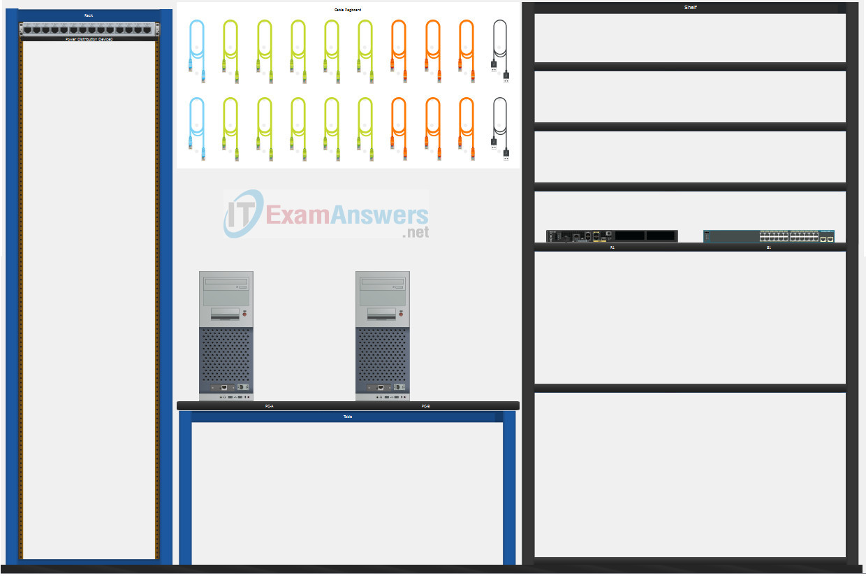
a. Build the network according to the logical topology by placing the required equipment in the wiring closet equipment rack.
b. Cable the network devices in the closet as shown in the topology diagram.
c. Connect the hosts as shown in the topology diagram.
Part 2: Develop an IP Addressing Scheme
In this part of the assessment you will develop an IP addressing scheme. You will subnet an IPv4 network to create two subnets with the required number of hosts. You will also subnet an IPv6 network. You will then assign the addresses according to the requirements below.
Work with the following information:
- IPv4 Network: 192.168.10.0/24
- Required number of hosts in IPv4 LAN 1: 100
- Required number of hosts in IPv4 LAN 2: 50
a. Record your subnet assignments according to the following requirements.
1) Assign the first IPv4 address of each subnet to a router interface
- LAN 1 is hosted on R1 G0/0/1
- LAN 2 is hosted on R1 G0/0/0
2) Assign the last IPv4 address of each subnet to the PC NIC.
3) Assign the second IPv4 address of LAN 1 to S1 SVI.
Part 3: Configure Basic Device Settings
Network devices must be configured over a direct console connection.
Step 1: Configure Basic Settings
a. Disable DNS lookup on R1 and S1
b. Configure router hostname using the name R1.
c. Configure switch hostname using the name S1.
d. Configure an appropriate banner on R1 and S1.
e. Allow console logins with the password [email protected]!
Step 2: Configure Interfaces
a. Configure R1 G0/0/0 and G0/0/1 interfaces using the addressing from the previous part of this assessment:
- Interface description
- IPv4 address / subnet mask
b. Configure the S1 VLAN 1 SVI interface using the addressing from the previous part of this assessment:
- Interface description
- IPv4 address / subnet mask
- The switch should be reachable from devices on other networks.
Part 4: Configure Security Settings on R1 and S1
Step 1: Configure enhanced password security
a. Configure NoOneShouldKnow as the encrypted privileged EXEC password
b. Encrypt all plaintext passwords
c. Set minimum password length to 10 on R1.
Step 2: Configure SSH on R1 and S1
a. Configure netsec.com as the domain name
b. Configure a local user netadmin with the encrypted password Ci$co12345
c. Set login on vty lines to use local database.
d. Configure the vty lines to accept SSH access only.
e. Generate an RSA crypto key using 1024 bits modulus.
Step 3: Secure switch ports on S1
a. Shut down all unused ports on S1.
b. Enter descriptions for all unused switch ports to indicate that they are intentionally shutdown.
Part 5: Configure the Hosts and Verify Connectivity
Configure both hosts with the IPv4 addresses that were assigned in Part 2 of this assessment.
ID: 002
Answers Key — 100% Score
Part 1: Build the Network
Placing Switch S1 and Router R1 to wiring closet equipment rack.
Using Copper Straight-Through cable to connect PC-A (FastEthernet0 port) and S1 (FastEthernet0/6 port)
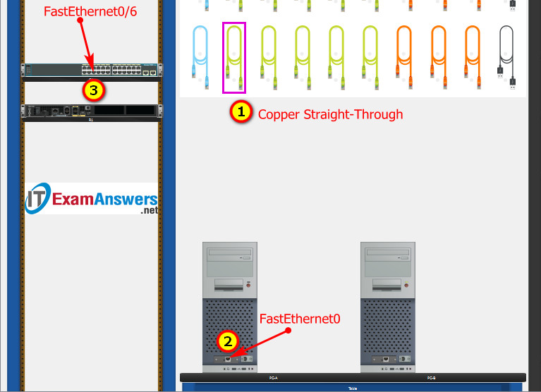
Same as above, using Copper Straight-Through cable to connect all devices as shown in the topology diagram.
ITN Final PT Skills Assessment (PTSA)

Turn-on PCs and Router R1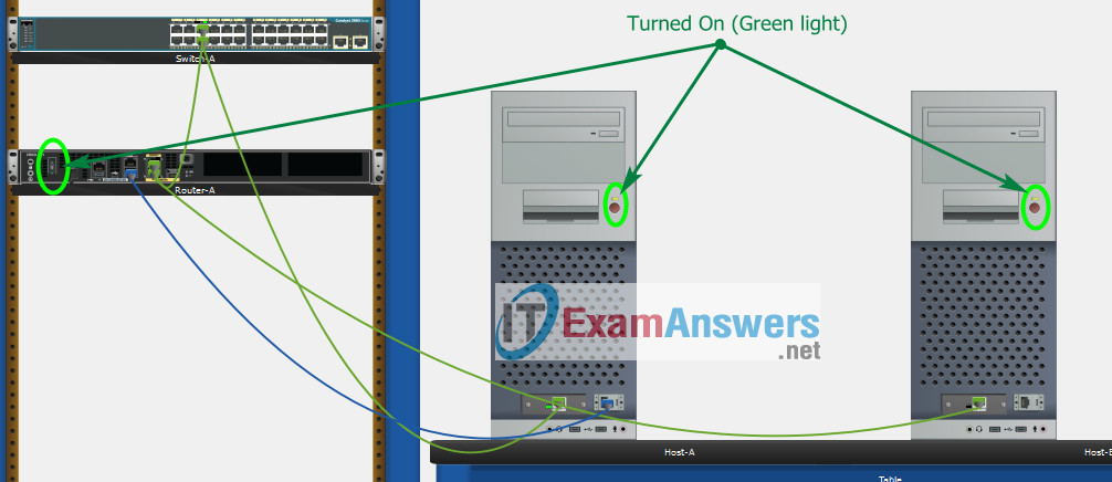
Part 2: Develop an IP Addressing Scheme
| Item | Requirements | IPv4 Address |
|---|---|---|
| Network Address | 192.168.10.0/24 | |
| LAN 1 subnet host requirements | 100 | 192.168.10.0/25 SM: 255.255.255.128 |
| LAN 2 subnet host requirements | 50 | 192.168.10.128/26 SM: 255.255.255.192 |
| R1 G0/0/1 | First host address in LAN 1 subnet | 192.168.10.1 |
| R1 G0/0/0 | First host address in LAN 2 subnet | 192.168.10.129 |
| S1 SVI | Second host address in LAN 1 subnet | 192.168.10.2 |
| PC-A | Last host address in LAN 1 subnet | 192.168.10.126 |
| PC-B | Last host address in LAN 2 subnet | 192.168.10.190 |
Configuration for router R1
Using line console to connect PC-A and Router R1
Click to PC-A —> Terminal app —> click OK
Router R1 configuration script
enable
configure terminal
no ip domain-lookup
hostname R1
banner motd #Unauthorized access to this device is prohibited!#

interface g0/0/0
description Connect to Subnet B
ip address 192.168.10.129 255.255.255.192
no shutdown
exit

interface g0/0/1
description Connect to Subnet A
ip address 192.168.10.1 255.255.255.128
no shutdown
exit

enable secret NoOneShouldKnow
service password-encryption
security passwords min-length 10

ip domain-name netsec.com
username netadmin secret Ci$co12345

line console 0
password [email protected]!
login
exit

line vty 0 15
transport input ssh
login local
exit

crypto key generate rsa
1024
exit
copy running-config startup-config
Configuration for Switch S1
Then, using Console cable to connect User-B and Switch
To show Console port on Switch, Right click Switch —> Inspect Rear —> Console port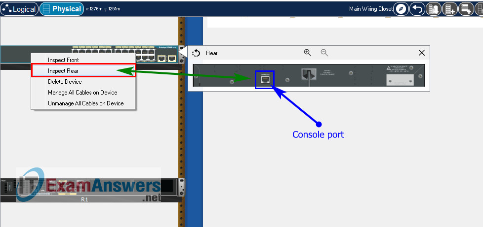
Switch S1 configuration script
enable
configure terminal
no ip domain-lookup
hostname S1
banner motd #Unauthorized access to this device is prohibited!#

interface vlan 1
description Switch Subnet A
ip address 192.168.10.2 255.255.255.128
no shutdown
exit

ip default-gateway 192.168.10.1

enable secret NoOneShouldKnow
service password-encryption

ip domain-name netsec.com
username netadmin secret Ci$co12345

line console 0
password [email protected]!
login
exit

line vty 0 15
transport input ssh
login local
exit

crypto key generate rsa
1024

int range f0/1 - 4, f0/7 - 24, g0/1 - 2
description Unused switch ports
shutdown

end
copy running-config startup-config
Part 5: Configure the Hosts and Verify Connectivity
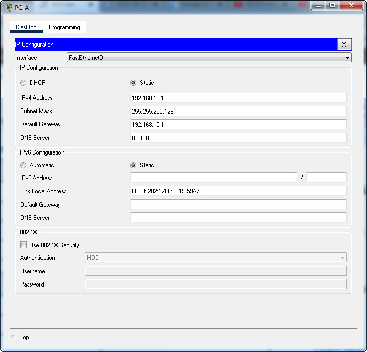
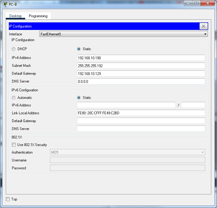
On PCs, go to Desktop tab —> IP Configuration menu
| PC-A Network Configuration | |
|---|---|
| IPv4 Address | 192.168.10.126 |
| Subnet Mask | 255.255.255.128 |
| IPv4 Default Gateway | 192.168.10.1 |
| PC-B Network Configuration | |
|---|---|
| IPv4 Address | 192.168.10.190 |
| Subnet Mask | 255.255.255.192 |
| IPv4 Default Gateway | 192.168.10.129 |
Download PDF & Packet Tracer files:
[sociallocker id=»57850″]
[/sociallocker]
ITN Final Skills Exam (PTSA)
ITN (Version 7.00) Final PT Skills Assessment (PTSA) Exam Answers
Topology
ITN Final PT Skills Assessment (PTSA)
Device Names Table
You will receive one of three possible scenarios. In order to use the logical topology diagram that is provided with the instructions, use the device names in the Device Names Table.
| Topology Diagram Name | Your Scenario Name |
|---|---|
| R1 | Central-RT |
| S1 | Central-SW |
| PC-A | User-A |
| PC-B | User-B |
Addressing Requirements Table
| Item | Requirements |
|---|---|
| Network Address | 192.168.10.0/24 |
| LAN 1 subnet host requirements | 100 |
| LAN 2 subnet host requirements | 50 |
| Central-RT G0/0/1 | First host address in LAN 1 subnet |
| Central-RT G0/0/0 | First host address in LAN 2 subnet |
| Central-SW SVI | Second host address in LAN 1 subnet |
| User-A | Last host address in LAN 1 subnet |
| User-B | Last host address in LAN 2 subnet |
ITN Final PT Skills Assessment (PTSA)
A few things to keep in mind while completing this activity:
- Do not use the browser Back button or close or reload any exam windows during the exam.
- Do not close Packet Tracer when you are done. It will close automatically.
- Click the Submit Assessment button in the browser window to submit your work.
Assessment Objectives
- Part 1: Build the Network
- Part 2: Develop an IP Addressing Scheme
- Part 3: Configure Basic Device Settings
- Part 4: Configure Security Settings on Central-RT and Central-SW
- Part 5: Configure the Hosts and Verify Connectivity
Instructions
In this assessment you will configure the Central-RT router and Central-SW switch, as you have done in the activities in this course. You will also connect two PCs using a switch and a router that are in the main wiring closet. You will subnet the 192.168.10.0/24 network to provide IPv4 addresses for two subnets that will support the required number of hosts. The larger subnet (LAN 1) requires 100 hosts and the smaller subnet (LAN 2) requires 50 hosts.
No subnet calculators may be used.
Part 1: Build the Network
a. Build the network according to the logical topology by placing the required equipment in the wiring closet equipment rack.
b. Cable the network devices in the closet as shown in the topology diagram.
c. Connect the hosts as shown in the topology diagram.
Part 2: Develop an IP Addressing Scheme
In this part of the assessment you will develop an IP addressing scheme. You will subnet an IPv4 network to create two subnets with the required number of hosts. You will also subnet an IPv6 network. You will then assign the addresses according to the requirements below.
Work with the following information:
- IPv4 Network: 192.168.10.0/24
- Required number of hosts in IPv4 LAN 1: 100
- Required number of hosts in IPv4 LAN 2: 50
a. Record your subnet assignments according to the following requirements.
1) Assign the first IPv4 address of each subnet to a router interface
- LAN 1 is hosted on Central-RT G0/0/1
- LAN 2 is hosted on Central-RT G0/0/0
2) Assign the last IPv4 address of each subnet to the PC NIC.
3) Assign the second IPv4 address of LAN 1 to Central-SW SVI.
Part 3: Configure Basic Device Settings
Network devices must be configured over a direct console connection.
Step 1: Configure Basic Settings
a. Disable DNS lookup on Central-RT and Central-SW
b. Configure router hostname using the name Central-RT.
c. Configure switch hostname using the name Central-SW.
d. Configure an appropriate banner on Central-RT and Central-SW.
e. Allow console logins with the password [email protected]!
Step 2: Configure Interfaces
a. Configure Central-RT G0/0/0 and G0/0/1 interfaces using the addressing from the previous part of this assessment:
- Interface description
- IPv4 address / subnet mask
b. Configure the Central-SW VLAN 1 SVI interface using the addressing from the previous part of this assessment:
- Interface description
- IPv4 address / subnet mask
- The switch should be reachable from devices on other networks.
Part 4: Configure Security Settings on Central-RT and Central-SW
Step 1: Configure enhanced password security
a. Configure NoOneShouldKnow as the encrypted privileged EXEC password
b. Encrypt all plaintext passwords
c. Set minimum password length to 10 on Central-RT.
Step 2: Configure SSH on Central-RT and Central-SW
a. Configure netsec.com as the domain name
b. Configure a local user netadmin with the encrypted password Ci$co12345
c. Set login on vty lines to use local database.
d. Configure the vty lines to accept SSH access only.
e. Generate an RSA crypto key using 1024 bits modulus.
Step 3: Secure switch ports on Central-SW
a. Shut down all unused ports on Central-SW.
b. Enter descriptions for all unused switch ports to indicate that they are intentionally shutdown.
Part 5: Configure the Hosts and Verify Connectivity
Configure both hosts with the IPv4 addresses that were assigned in Part 2 of this assessment.
ID: 012
Answers Key
Part 1: Build the Network
Placing Switch Central-SW and Router Central-RT to wiring closet equipment rack.
Using Copper Straight-Through cable to connect User-A (FastEthernet0 port) and Central-SW (FastEthernet0/6 port)
Same as above, using Copper Straight-Through cable to connect all devices as shown in the topology diagram.
ITN Final PT Skills Assessment (PTSA)
Turn-on PCs and Router Central-RT
Part 2: Develop an IP Addressing Scheme
| Item | Requirements | IPv4 Address |
|---|---|---|
| Network Address | 192.168.10.0/24 | |
| LAN 1 subnet host requirements | 100 | 192.168.10.0/25 SM: 255.255.255.128 |
| LAN 2 subnet host requirements | 50 | 192.168.10.128/26 SM: 255.255.255.192 |
| Central-RT G0/0/1 | First host address in LAN 1 subnet | 192.168.10.1 |
| Central-RT G0/0/0 | First host address in LAN 2 subnet | 192.168.10.129 |
| Central-SW SVI | Second host address in LAN 1 subnet | 192.168.10.2 |
| User-A | Last host address in LAN 1 subnet | 192.168.10.126 |
| User-B | Last host address in LAN 2 subnet | 192.168.10.190 |
Using line console to connect User-A and Router
Click to User-A —> Terminal app —> click OK
Router Central-RT configuration script
enable
configure terminal
no ip domain-lookup
hostname Central-RT
banner motd #Unauthorized access to this device is prohibited!#

interface g0/0/0
description Connect to Subnet B
ip address 192.168.10.129 255.255.255.192
no shutdown
exit

interface g0/0/1
description Connect to Subnet A
ip address 192.168.10.1 255.255.255.128
no shutdown
exit

enable secret NoOneShouldKnow
service password-encryption
security passwords min-length 10

ip domain-name netsec.com
username netadmin secret Ci$co12345

line console 0
password [email protected]!
login
exit

line vty 0 15
transport input ssh
login local
exit

crypto key generate rsa
1024
exit
copy running-config startup-config
Configuration for Switch Central-SW
Then, using Console cable to connect User-B and Switch
To show Console port on Switch, Right click Switch —> Inspect Rear —> Console port
Switch Central-SW configuration script
enable
configure terminal
no ip domain-lookup
hostname Central-SW
banner motd #Unauthorized access to this device is prohibited!#

interface vlan 1
description Switch Subnet A
ip address 192.168.10.2 255.255.255.128
no shutdown
exit

ip default-gateway 192.168.10.1

enable secret NoOneShouldKnow
service password-encryption

ip domain-name netsec.com
username netadmin secret Ci$co12345

line console 0
password [email protected]!
login
exit

line vty 0 15
transport input ssh
login local
exit

crypto key generate rsa
1024

int range f0/1 - 4, f0/7 - 24, g0/1 - 2
description Unused switch ports
shutdown

end
copy running-config startup-config
Part 5: Configure the Hosts and Verify Connectivity
On PCs, go to Desktop tab —> IP Configuration menu
| PC-A Network Configuration | |
|---|---|
| IPv4 Address | 192.168.10.126 |
| Subnet Mask | 255.255.255.128 |
| IPv4 Default Gateway | 192.168.10.1 |
| PC-B Network Configuration | |
|---|---|
| IPv4 Address | 192.168.10.190 |
| Subnet Mask | 255.255.255.192 |
| IPv4 Default Gateway | 192.168.10.129 |
Download PDF & Packet Tracer files:
[sociallocker id=»57850″]
[/sociallocker]
ITN Final Skills Exam (PTSA)
ITN (Version 7.00) Final PT Skills Assessment (PTSA) Exam Answers
Topology
ITN Final PT Skills Assessment (PTSA)
Device Names Table
You will receive one of three possible scenarios. In order to use the logical topology diagram that is provided with the instructions, use the device names in the Device Names Table.
| Topology Diagram Name | Your Scenario Name |
|---|---|
| R1 | Central-RT |
| S1 | Central-SW |
| PC-A | User-A |
| PC-B | User-B |
Addressing Requirements Table
| Item | Requirements |
|---|---|
| Network Address | 209.165.201.0/24 |
| LAN 1 subnet host requirements | 29 |
| LAN 2 subnet host requirements | 17 |
| Central-RT G0/0/1 | First host address in LAN 1 subnet |
| Central-RT G0/0/0 | First host address in LAN 2 subnet |
| Central-SW SVI | Second host address in LAN 1 subnet |
| User-A | Last host address in LAN 1 subnet |
| User-B | Last host address in LAN 2 subnet |
ITN Final PT Skills Assessment (PTSA)
A few things to keep in mind while completing this activity:
- Do not use the browser Back button or close or reload any exam windows during the exam.
- Do not close Packet Tracer when you are done. It will close automatically.
- Click the Submit Assessment button in the browser window to submit your work.
Assessment Objectives
- Part 1: Build the Network
- Part 2: Develop an IP Addressing Scheme
- Part 3: Configure Basic Device Settings
- Part 4: Configure Security Settings on Central-RT and Central-SW
- Part 5: Configure the Hosts and Verify Connectivity
Instructions
In this assessment you will configure the Central-RT router and Central-SW switch, as you have done in the activities in this course. You will also connect two PCs using a switch and a router that are in the main wiring closet. You will subnet the 209.165.201.0/24 network to provide IPv4 addresses for two subnets that will support the required number of hosts. The larger subnet (LAN 1) requires 29 hosts and the smaller subnet (LAN 2) requires 17 hosts.
No subnet calculators may be used.
Part 1: Build the Network
a. Build the network according to the logical topology by placing the required equipment in the wiring closet equipment rack.
b. Cable the network devices in the closet as shown in the topology diagram.
c. Connect the hosts as shown in the topology diagram.
Part 2: Develop an IP Addressing Scheme
In this part of the assessment you will develop an IP addressing scheme. You will subnet an IPv4 network to create two subnets with the required number of hosts. You will also subnet an IPv6 network. You will then assign the addresses according to the requirements below.
Work with the following information:
- IPv4 Network: 209.165.201.0/24
- Required number of hosts in IPv4 LAN 1: 29
- Required number of hosts in IPv4 LAN 2: 17
a. Record your subnet assignments according to the following requirements.
1) Assign the first IPv4 address of each subnet to a router interface
- LAN 1 is hosted on Central-RT G0/0/1
- LAN 2 is hosted on Central-RT G0/0/0
2) Assign the last IPv4 address of each subnet to the PC NIC.
3) Assign the second IPv4 address of LAN 1 to Central-SW SVI.
Part 3: Configure Basic Device Settings
Network devices must be configured over a direct console connection.
Step 1: Configure Basic Settings
a. Disable DNS lookup on Central-RT and Central-SW
b. Configure router hostname using the name Central-RT.
c. Configure switch hostname using the name Central-SW.
d. Configure an appropriate banner on Central-RT and Central-SW.
e. Allow console logins with the password [email protected]!
Step 2: Configure Interfaces
a. Configure Central-RT G0/0/0 and G0/0/1 interfaces using the addressing from the previous part of this assessment:
- Interface description
- IPv4 address / subnet mask
b. Configure the Central-SW VLAN 1 SVI interface using the addressing from the previous part of this assessment:
- Interface description
- IPv4 address / subnet mask
- The switch should be reachable from devices on other networks.
Part 4: Configure Security Settings on Central-RT and Central-SW
Step 1: Configure enhanced password security
a. Configure NoOneShouldKnow as the encrypted privileged EXEC password
b. Encrypt all plaintext passwords
c. Set minimum password length to 10 on Central-RT.
Step 2: Configure SSH on Central-RT and Central-SW
a. Configure netsec.com as the domain name
b. Configure a local user netadmin with the encrypted password Ci$co12345
c. Set login on vty lines to use local database.
d. Configure the vty lines to accept SSH access only.
e. Generate an RSA crypto key using 1024 bits modulus.
Step 3: Secure switch ports on Central-SW
a. Shut down all unused ports on Central-SW.
b. Enter descriptions for all unused switch ports to indicate that they are intentionally shutdown.
Part 5: Configure the Hosts and Verify Connectivity
Configure both hosts with the IPv4 addresses that were assigned in Part 2 of this assessment.
ID: 211
Answers Key — 100% Score
Part 1: Build the Network
Placing Switch Central-SW and Router Central-RT to wiring closet equipment rack.
Using Copper Straight-Through cable to connect User-A (FastEthernet0 port) and Central-SW (FastEthernet0/6 port)
Same as above, using Copper Straight-Through cable to connect all devices as shown in the topology diagram.
ITN Final PT Skills Assessment (PTSA)
Turn-on PCs and Router Central-RT
Part 2: Develop an IP Addressing Scheme
| Item | Requirements | IPv4 Address |
|---|---|---|
| Network Address | 209.165.201.0/24 | |
| LAN 1 subnet host requirements | 29 | 209.165.201.0/27 SM: 255.255.255.224 |
| LAN 2 subnet host requirements | 17 | 209.165.201.32/27 SM: 255.255.255.224 |
| Central-RT G0/0/1 | First host address in LAN 1 subnet | 209.165.201.1 |
| Central-RT G0/0/0 | First host address in LAN 2 subnet | 209.165.201.33 |
| Central-SW SVI | Second host address in LAN 1 subnet | 209.165.201.2 |
| User-A | Last host address in LAN 1 subnet | 209.165.201.30 |
| User-B | Last host address in LAN 2 subnet | 209.165.201.62 |
Using line console to connect User-A and Router
Click to User-A —> Terminal app —> click OK
Router Central-RT configuration script
enable
configure terminal
no ip domain-lookup
hostname Central-RT
banner motd #Unauthorized access to this device is prohibited!#

interface g0/0/0
description Connect to Subnet B
ip address 209.165.201.33 255.255.255.224
no shutdown
exit

interface g0/0/1
description Connect to Subnet A
ip address 209.165.201.1 255.255.255.224
no shutdown
exit

enable secret NoOneShouldKnow
service password-encryption
security passwords min-length 10

ip domain-name netsec.com
username netadmin secret Ci$co12345

line console 0
password [email protected]!
login
exit

line vty 0 15
transport input ssh
login local
exit

crypto key generate rsa
1024
exit
copy running-config startup-config
Configuration for Switch Central-SW
Then, using Console cable to connect User-B and Switch
To show Console port on Switch, Right click Switch —> Inspect Rear —> Console port
Switch Central-SW configuration script
enable
configure terminal
no ip domain-lookup
hostname Central-SW
banner motd #Unauthorized access to this device is prohibited!#

interface vlan 1
description Switch Subnet A
ip address 209.165.201.2 255.255.255.224
no shutdown
exit

ip default-gateway 209.165.201.1

enable secret NoOneShouldKnow
service password-encryption

ip domain-name netsec.com
username netadmin secret Ci$co12345

line console 0
password [email protected]!
login
exit

line vty 0 15
transport input ssh
login local
exit

crypto key generate rsa
1024

int range f0/1 - 4, f0/7 - 24, g0/1 - 2
description Unused switch ports
shutdown

end
copy running-config startup-config
Part 5: Configure the Hosts and Verify Connectivity
On PCs, go to Desktop tab —> IP Configuration menu
| PC-A Network Configuration | |
|---|---|
| IPv4 Address | 209.165.201.30 |
| Subnet Mask | 255.255.255.224 |
| IPv4 Default Gateway | 209.165.201.1 |
| PC-B Network Configuration | |
|---|---|
| IPv4 Address | 209.165.201.62 |
| Subnet Mask | 255.255.255.224 |
| IPv4 Default Gateway | 209.165.201.33 |
Download PDF & Packet Tracer files:
[sociallocker id=»57850″]
[/sociallocker]
ITN Final Skills Exam (PTSA)
ITN (Version 7.00) Final PT Skills Assessment (PTSA) Exam Answers
Topology
ITN Final PT Skills Assessment (PTSA)
Device Names Table
You will receive one of three possible scenarios. In order to use the logical topology diagram that is provided with the instructions, use the device names in the Device Names Table.
| Topology Diagram Name | Your Scenario Name |
|---|---|
| R1 | Router-A |
| S1 | Switch-A |
| PC-A | Host-A |
| PC-B | Host-B |
Addressing Requirements Table
| Item | Requirements |
|---|---|
| Network Address | 172.16.1.0/24 |
| LAN 1 subnet host requirements | 60 |
| LAN 2 subnet host requirements | 20 |
| Router-A G0/0/1 | First host address in LAN 1 subnet |
| Router-A G0/0/0 | First host address in LAN 2 subnet |
| Switch-A SVI | Second host address in LAN 1 subnet |
| User-A | Last host address in LAN 1 subnet |
| User-B | Last host address in LAN 2 subnet |
ITN Final PT Skills Assessment (PTSA)
A few things to keep in mind while completing this activity:
- Do not use the browser Back button or close or reload any exam windows during the exam.
- Do not close Packet Tracer when you are done. It will close automatically.
- Click the Submit Assessment button in the browser window to submit your work.
Assessment Objectives
- Part 1: Build the Network
- Part 2: Develop an IP Addressing Scheme
- Part 3: Configure Basic Device Settings
- Part 4: Configure Security Settings on Router-A and Switch-A
- Part 5: Configure the Hosts and Verify Connectivity
Instructions
In this assessment you will configure the Router-A router and Switch-A switch, as you have done in the activities in this course. You will also connect two PCs using a switch and a router that are in the main wiring closet. You will subnet the 172.16.1.0/24 network to provide IPv4 addresses for two subnets that will support the required number of hosts. The larger subnet (LAN 1) requires 60 hosts and the smaller subnet (LAN 2) requires 20 hosts.
No subnet calculators may be used.
Part 1: Build the Network
a. Build the network according to the logical topology by placing the required equipment in the wiring closet equipment rack.
b. Cable the network devices in the closet as shown in the topology diagram.
c. Connect the hosts as shown in the topology diagram.
Part 2: Develop an IP Addressing Scheme
In this part of the assessment you will develop an IP addressing scheme. You will subnet an IPv4 network to create two subnets with the required number of hosts. You will also subnet an IPv6 network. You will then assign the addresses according to the requirements below.
Work with the following information:
- IPv4 Network: 172.16.1.0/24
- Required number of hosts in IPv4 LAN 1: 60
- Required number of hosts in IPv4 LAN 2: 20
a. Record your subnet assignments according to the following requirements.
1) Assign the first IPv4 address of each subnet to a router interface
- LAN 1 is hosted on Router-A G0/0/1
- LAN 2 is hosted on Router-A G0/0/0
2) Assign the last IPv4 address of each subnet to the PC NIC.
3) Assign the second IPv4 address of LAN 1 to Switch-A SVI.
Part 3: Configure Basic Device Settings
Network devices must be configured over a direct console connection.
Step 1: Configure Basic Settings
a. Disable DNS lookup on Router-A and Switch-A
b. Configure router hostname using the name Router-A.
c. Configure switch hostname using the name Switch-A.
d. Configure an appropriate banner on Router-A and Switch-A.
e. Allow console logins with the password [email protected]!
Step 2: Configure Interfaces
a. Configure Router-A G0/0/0 and G0/0/1 interfaces using the addressing from the previous part of this assessment:
- Interface description
- IPv4 address / subnet mask
b. Configure the Switch-A VLAN 1 SVI interface using the addressing from the previous part of this assessment:
- Interface description
- IPv4 address / subnet mask
- The switch should be reachable from devices on other networks.
Part 4: Configure Security Settings on Router-A and Switch-A
Step 1: Configure enhanced password security
a. Configure NoOneShouldKnow as the encrypted privileged EXEC password
b. Encrypt all plaintext passwords
c. Set minimum password length to 10 on Router-A.
Step 2: Configure SSH on Router-A and Switch-A
a. Configure netsec.com as the domain name
b. Configure a local user netadmin with the encrypted password Ci$co12345
c. Set login on vty lines to use local database.
d. Configure the vty lines to accept SSH access only.
e. Generate an RSA crypto key using 1024 bits modulus.
Step 3: Secure switch ports on Switch-A
a. Shut down all unused ports on Switch-A.
b. Enter descriptions for all unused switch ports to indicate that they are intentionally shutdown.
Part 5: Configure the Hosts and Verify Connectivity
Configure both hosts with the IPv4 addresses that were assigned in Part 2 of this assessment.
ID: 120
Answers Key — 100% Score
Part 1: Build the Network
Placing Switch Switch-A and Router Router-A to wiring closet equipment rack.
Using Copper Straight-Through cable to connect User-A (FastEthernet0 port) and Switch-A (FastEthernet0/6 port)
Same as above, using Copper Straight-Through cable to connect all devices as shown in the topology diagram.
ITN Final PT Skills Assessment (PTSA)
Turn-on PCs and Router Router-A
Part 2: Develop an IP Addressing Scheme
| Item | Requirements | IPv4 Address |
|---|---|---|
| Network Address | 172.16.1.0/24 | |
| LAN 1 subnet host requirements | 60 | 172.16.1.0/26 SM: 255.255.255.192 |
| LAN 2 subnet host requirements | 20 | 172.16.1.64/27 SM: 255.255.255.224 |
| Router-A G0/0/1 | First host address in LAN 1 subnet | 172.16.1.1 |
| Router-A G0/0/0 | First host address in LAN 2 subnet | 172.16.1.65 |
| Switch-A SVI | Second host address in LAN 1 subnet | 172.16.1.2 |
| User-A | Last host address in LAN 1 subnet | 172.16.1.62 |
| User-B | Last host address in LAN 2 subnet | 172.16.1.94 |
Using line console to connect User-A and Router
Click to User-A —> Terminal app —> click OK
Router Router-A configuration script
enable
configure terminal
no ip domain-lookup
hostname Router-A
banner motd #Unauthorized access to this device is prohibited!#

interface g0/0/0
description Connect to Subnet B
ip address 172.16.1.65 255.255.255.224
no shutdown
exit

interface g0/0/1
description Connect to Subnet A
ip address 172.16.1.1 255.255.255.192
no shutdown
exit

enable secret NoOneShouldKnow
service password-encryption
security passwords min-length 10

ip domain-name netsec.com
username netadmin secret Ci$co12345

line console 0
password [email protected]!
login
exit

line vty 0 15
transport input ssh
login local
exit

crypto key generate rsa
1024
exit
copy running-config startup-config
Configuration for Switch-A
Then, using Console cable to connect User-B and Switch
To show Console port on Switch, Right click Switch —> Inspect Rear —> Console port
Switch Switch-A configuration script
enable
configure terminal
no ip domain-lookup
hostname Switch-A
banner motd #Unauthorized access to this device is prohibited!#

interface vlan 1
description Switch Subnet A
ip address 172.16.1.2 255.255.255.192
no shutdown
exit

ip default-gateway 172.16.1.1

enable secret NoOneShouldKnow
service password-encryption

ip domain-name netsec.com
username netadmin secret Ci$co12345

line console 0
password [email protected]!
login
exit

line vty 0 15
transport input ssh
login local
exit

crypto key generate rsa
1024

int range f0/1 - 4, f0/7 - 24, g0/1 - 2
description Unused switch ports
shutdown

end
copy running-config startup-config
Part 5: Configure the Hosts and Verify Connectivity
On PCs, go to Desktop tab —> IP Configuration menu
| PC-A Network Configuration | |
|---|---|
| IPv4 Address | 172.16.1.62 |
| Subnet Mask | 255.255.255.192 |
| IPv4 Default Gateway | 172.16.1.1 |
| PC-B Network Configuration | |
|---|---|
| IPv4 Address | 172.16.1.94 |
| Subnet Mask | 255.255.255.224 |
| IPv4 Default Gateway | 172.16.1.65 |
Download PDF & Packet Tracer files:
[sociallocker id=»57850″]
[/sociallocker]
ITN Final Skills Exam (PTSA)
ITN (Version 7.00) Final PT Skills Assessment (PTSA) Exam Answers
Topology
ITN Final PT Skills Assessment (PTSA)
Device Names Table
You will receive one of three possible scenarios. In order to use the logical topology diagram that is provided with the instructions, use the device names in the Device Names Table.
| Topology Diagram Name | Your Scenario Name |
|---|---|
| R1 | Central-RT |
| S1 | Central-SW |
| PC-A | User-A |
| PC-B | User-B |
Addressing Requirements Table
| Item | Requirements |
|---|---|
| Network Address | 192.168.10.0/24 |
| LAN 1 subnet host requirements | 100 |
| LAN 2 subnet host requirements | 50 |
| Central-RT G0/0/1 | First host address in LAN 1 subnet |
| Central-RT G0/0/0 | First host address in LAN 2 subnet |
| Central-SW SVI | Second host address in LAN 1 subnet |
| User-A | Last host address in LAN 1 subnet |
| User-B | Last host address in LAN 2 subnet |
ITN Final PT Skills Assessment (PTSA)
A few things to keep in mind while completing this activity:
- Do not use the browser Back button or close or reload any exam windows during the exam.
- Do not close Packet Tracer when you are done. It will close automatically.
- Click the Submit Assessment button in the browser window to submit your work.
Assessment Objectives
- Part 1: Build the Network
- Part 2: Develop an IP Addressing Scheme
- Part 3: Configure Basic Device Settings
- Part 4: Configure Security Settings on Central-RT and Central-SW
- Part 5: Configure the Hosts and Verify Connectivity
Instructions
In this assessment you will configure the Central-RT router and Central-SW switch, as you have done in the activities in this course. You will also connect two PCs using a switch and a router that are in the main wiring closet. You will subnet the 192.168.10.0/24 network to provide IPv4 addresses for two subnets that will support the required number of hosts. The larger subnet (LAN 1) requires 100 hosts and the smaller subnet (LAN 2) requires 50 hosts.
No subnet calculators may be used.
Part 1: Build the Network
a. Build the network according to the logical topology by placing the required equipment in the wiring closet equipment rack.
b. Cable the network devices in the closet as shown in the topology diagram.
c. Connect the hosts as shown in the topology diagram.
Part 2: Develop an IP Addressing Scheme
In this part of the assessment you will develop an IP addressing scheme. You will subnet an IPv4 network to create two subnets with the required number of hosts. You will also subnet an IPv6 network. You will then assign the addresses according to the requirements below.
Work with the following information:
- IPv4 Network: 192.168.10.0/24
- Required number of hosts in IPv4 LAN 1: 100
- Required number of hosts in IPv4 LAN 2: 50
a. Record your subnet assignments according to the following requirements.
1) Assign the first IPv4 address of each subnet to a router interface
- LAN 1 is hosted on Central-RT G0/0/1
- LAN 2 is hosted on Central-RT G0/0/0
2) Assign the last IPv4 address of each subnet to the PC NIC.
3) Assign the second IPv4 address of LAN 1 to Central-SW SVI.
Part 3: Configure Basic Device Settings
Network devices must be configured over a direct console connection.
Step 1: Configure Basic Settings
a. Disable DNS lookup on Central-RT and Central-SW
b. Configure router hostname using the name Central-RT.
c. Configure switch hostname using the name Central-SW.
d. Configure an appropriate banner on Central-RT and Central-SW.
e. Allow console logins with the password [email protected]!
Step 2: Configure Interfaces
a. Configure Central-RT G0/0/0 and G0/0/1 interfaces using the addressing from the previous part of this assessment:
- Interface description
- IPv4 address / subnet mask
b. Configure the Central-SW VLAN 1 SVI interface using the addressing from the previous part of this assessment:
- Interface description
- IPv4 address / subnet mask
- The switch should be reachable from devices on other networks.
Part 4: Configure Security Settings on Central-RT and Central-SW
Step 1: Configure enhanced password security
a. Configure DontTellAnyone as the encrypted privileged EXEC password
b. Encrypt all plaintext passwords
c. Set minimum password length to 10 on Central-RT.
Step 2: Configure SSH on Central-RT and Central-SW
a. Configure netsec.com as the domain name
b. Configure a local user netadmin with the encrypted password Ci$co12345
c. Set login on vty lines to use local database.
d. Configure the vty lines to accept SSH access only.
e. Generate an RSA crypto key using 1024 bits modulus.
Step 3: Secure switch ports on Central-SW
a. Shut down all unused ports on Central-SW.
b. Enter descriptions for all unused switch ports to indicate that they are intentionally shutdown.
Part 5: Configure the Hosts and Verify Connectivity
Configure both hosts with the IPv4 addresses that were assigned in Part 2 of this assessment.
ID: 011
Answers Key
Part 1: Build the Network
Placing Switch Central-SW and Router Central-RT to wiring closet equipment rack.
Using Copper Straight-Through cable to connect User-A (FastEthernet0 port) and Central-SW (FastEthernet0/6 port)
Same as above, using Copper Straight-Through cable to connect all devices as shown in the topology diagram.
ITN Final PT Skills Assessment (PTSA)
Turn-on PCs and Router Central-RT
Part 2: Develop an IP Addressing Scheme
| Item | Requirements | IPv4 Address |
|---|---|---|
| Network Address | 192.168.10.0/24 | |
| LAN 1 subnet host requirements | 100 | 192.168.10.0/25 SM: 255.255.255.128 |
| LAN 2 subnet host requirements | 50 | 192.168.10.128/26 SM: 255.255.255.192 |
| Central-RT G0/0/1 | First host address in LAN 1 subnet | 192.168.10.1 |
| Central-RT G0/0/0 | First host address in LAN 2 subnet | 192.168.10.129 |
| Central-SW SVI | Second host address in LAN 1 subnet | 192.168.10.2 |
| User-A | Last host address in LAN 1 subnet | 192.168.10.126 |
| User-B | Last host address in LAN 2 subnet | 192.168.10.190 |
Using line console to connect User-A and Router
Click to User-A —> Terminal app —> click OK
Router Central-RT configuration script
enable
configure terminal
no ip domain-lookup
hostname Central-RT
banner motd #Unauthorized access to this device is prohibited!#

interface g0/0/0
description Connect to Subnet B
ip address 192.168.10.129 255.255.255.192
no shutdown
exit

interface g0/0/1
description Connect to Subnet A
ip address 192.168.10.1 255.255.255.128
no shutdown
exit

enable secret DontTellAnyone
service password-encryption
security passwords min-length 10

ip domain-name netsec.com
username netadmin secret Ci$co12345

line console 0
password [email protected]!
login
exit

line vty 0 15
transport input ssh
login local
exit

crypto key generate rsa
1024
exit
copy running-config startup-config
Configuration for Switch Central-SW
Then, using Console cable to connect User-B and Switch
To show Console port on Switch, Right click Switch —> Inspect Rear —> Console port
Switch Central-SW configuration script
enable
configure terminal
no ip domain-lookup
hostname Central-SW
banner motd #Unauthorized access to this device is prohibited!#

interface vlan 1
description Switch Subnet A
ip address 192.168.10.2 255.255.255.128
no shutdown
exit

ip default-gateway 192.168.10.1

enable secret DontTellAnyone
service password-encryption

ip domain-name netsec.com
username netadmin secret Ci$co12345

line console 0
password [email protected]!
login
exit

line vty 0 15
transport input ssh
login local
exit

crypto key generate rsa
1024

int range f0/1 - 4, f0/7 - 24, g0/1 - 2
description Unused switch ports
shutdown

end
copy running-config startup-config
Part 5: Configure the Hosts and Verify Connectivity
On PCs, go to Desktop tab —> IP Configuration menu
| PC-A Network Configuration | |
|---|---|
| IPv4 Address | 192.168.10.126 |
| Subnet Mask | 255.255.255.128 |
| IPv4 Default Gateway | 192.168.10.1 |
| PC-B Network Configuration | |
|---|---|
| IPv4 Address | 192.168.10.190 |
| Subnet Mask | 255.255.255.192 |
| IPv4 Default Gateway | 192.168.10.129 |
Download PDF & Packet Tracer files:
[sociallocker id=»57850″]
[/sociallocker]
ITN Final Skills Exam (PTSA)
ITN (Version 7.00) Final PT Skills Assessment (PTSA) Exam Answers
Topology
ITN Final PT Skills Assessment (PTSA)
Device Names Table
You will receive one of three possible scenarios. In order to use the logical topology diagram that is provided with the instructions, use the device names in the Device Names Table.
| Topology Diagram Name | Your Scenario Name |
|---|---|
| R1 | Router-A |
| S1 | Switch-A |
| PC-A | Host-A |
| PC-B | Host-B |
Addressing Requirements Table
| Item | Requirements |
|---|---|
| Network Address | 192.168.10.0/24 |
| LAN 1 subnet host requirements | 100 |
| LAN 2 subnet host requirements | 50 |
| Router-A G0/0/1 | First host address in LAN 1 subnet |
| Router-A G0/0/0 | First host address in LAN 2 subnet |
| Switch-A SVI | Second host address in LAN 1 subnet |
| Host-A | Last host address in LAN 1 subnet |
| Host-B | Last host address in LAN 2 subnet |
ITN Final PT Skills Assessment (PTSA)
A few things to keep in mind while completing this activity:
- Do not use the browser Back button or close or reload any exam windows during the exam.
- Do not close Packet Tracer when you are done. It will close automatically.
- Click the Submit Assessment button in the browser window to submit your work.
Assessment Objectives
- Part 1: Build the Network
- Part 2: Develop an IP Addressing Scheme
- Part 3: Configure Basic Device Settings
- Part 4: Configure Security Settings on Router-A and Switch-A
- Part 5: Configure the Hosts and Verify Connectivity
Instructions
In this assessment you will configure the Router-A router and Switch-A switch, as you have done in the activities in this course. You will also connect two PCs using a switch and a router that are in the main wiring closet. You will subnet the 192.168.10.0/24 network to provide IPv4 addresses for two subnets that will support the required number of hosts. The larger subnet (LAN 1) requires 100 hosts and the smaller subnet (LAN 2) requires 50 hosts.
No subnet calculators may be used.
Part 1: Build the Network
a. Build the network according to the logical topology by placing the required equipment in the wiring closet equipment rack.
b. Cable the network devices in the closet as shown in the topology diagram.
c. Connect the hosts as shown in the topology diagram.
Part 2: Develop an IP Addressing Scheme
In this part of the assessment you will develop an IP addressing scheme. You will subnet an IPv4 network to create two subnets with the required number of hosts. You will also subnet an IPv6 network. You will then assign the addresses according to the requirements below.
Work with the following information:
- IPv4 Network: 192.168.10.0/24
- Required number of hosts in IPv4 LAN 1: 100
- Required number of hosts in IPv4 LAN 2: 50
a. Record your subnet assignments according to the following requirements.
1) Assign the first IPv4 address of each subnet to a router interface
- LAN 1 is hosted on Router-A G0/0/1
- LAN 2 is hosted on Router-A G0/0/0
2) Assign the last IPv4 address of each subnet to the PC NIC.
3) Assign the second IPv4 address of LAN 1 to Switch-A SVI.
Part 3: Configure Basic Device Settings
Network devices must be configured over a direct console connection.
Step 1: Configure Basic Settings
a. Disable DNS lookup on Router-A and Switch-A
b. Configure router hostname using the name Router-A.
c. Configure switch hostname using the name Switch-A.
d. Configure an appropriate banner on Router-A and Switch-A.
e. Allow console logins with the password [email protected]!
Step 2: Configure Interfaces
a. Configure Router-A G0/0/0 and G0/0/1 interfaces using the addressing from the previous part of this assessment:
- Interface description
- IPv4 address / subnet mask
b. Configure the Switch-A VLAN 1 SVI interface using the addressing from the previous part of this assessment:
- Interface description
- IPv4 address / subnet mask
- The switch should be reachable from devices on other networks.
Part 4: Configure Security Settings on Router-A and Switch-A
Step 1: Configure enhanced password security
a. Configure DontTellAnyone as the encrypted privileged EXEC password
b. Encrypt all plaintext passwords
c. Set minimum password length to 10 on Router-A.
Step 2: Configure SSH on Router-A and Switch-A
a. Configure netsec.com as the domain name
b. Configure a local user netadmin with the encrypted password Ci$co12345
c. Set login on vty lines to use local database.
d. Configure the vty lines to accept SSH access only.
e. Generate an RSA crypto key using 1024 bits modulus.
Step 3: Secure switch ports on Switch-A
a. Shut down all unused ports on Switch-A.
b. Enter descriptions for all unused switch ports to indicate that they are intentionally shutdown.
Part 5: Configure the Hosts and Verify Connectivity
Configure both hosts with the IPv4 addresses that were assigned in Part 2 of this assessment.
ID: 021
Answers Key
Part 1: Build the Network
Placing Switch Switch-A and Router Router-A to wiring closet equipment rack.
Using Copper Straight-Through cable to connect Host-A (FastEthernet0 port) and Switch-A (FastEthernet0/6 port)
Same as above, using Copper Straight-Through cable to connect all devices as shown in the topology diagram.
ITN Final PT Skills Assessment (PTSA)
Turn-on PCs and Router Router-A
Part 2: Develop an IP Addressing Scheme
| Item | Requirements | IPv4 Address |
|---|---|---|
| Network Address | 192.168.10.0/24 | |
| LAN 1 subnet host requirements | 100 | 192.168.10.0/25 SM: 255.255.255.128 |
| LAN 2 subnet host requirements | 50 | 192.168.10.128/26 SM: 255.255.255.192 |
| Router-A G0/0/1 | First host address in LAN 1 subnet | 192.168.10.1 |
| Router-A G0/0/0 | First host address in LAN 2 subnet | 192.168.10.129 |
| Switch-A SVI | Second host address in LAN 1 subnet | 192.168.10.2 |
| Host-A | Last host address in LAN 1 subnet | 192.168.10.126 |
| Host-B | Last host address in LAN 2 subnet | 192.168.10.190 |
Using line console to connect Host-A and Router
Click to Host-A —> Terminal app —> click OK
Router Router-A configuration script
enable
configure terminal
no ip domain-lookup
hostname Router-A
banner motd #Unauthorized access to this device is prohibited!#

interface g0/0/0
description Connect to Subnet B
ip address 192.168.10.129 255.255.255.192
no shutdown
exit

interface g0/0/1
description Connect to Subnet A
ip address 192.168.10.1 255.255.255.128
no shutdown
exit

enable secret DontTellAnyone
service password-encryption
security passwords min-length 10

ip domain-name netsec.com
username netadmin secret Ci$co12345

line console 0
password [email protected]!
login
exit

line vty 0 15
transport input ssh
login local
exit

crypto key generate rsa
1024
exit
copy running-config startup-config
Configuration for Switch Switch-A
Then, using Console cable to connect Host-B and Switch
To show Console port on Switch, Right click Switch —> Inspect Rear —> Console port
Switch Switch-A configuration script
enable
configure terminal
no ip domain-lookup
hostname Switch-A
banner motd #Unauthorized access to this device is prohibited!#

interface vlan 1
description Switch Subnet A
ip address 192.168.10.2 255.255.255.128
no shutdown
exit

ip default-gateway 192.168.10.1

enable secret DontTellAnyone
service password-encryption

ip domain-name netsec.com
username netadmin secret Ci$co12345

line console 0
password [email protected]!
login
exit

line vty 0 15
transport input ssh
login local
exit

crypto key generate rsa
1024

int range f0/1 - 4, f0/7 - 24, g0/1 - 2
description Unused switch ports
shutdown

end
copy running-config startup-config
Part 5: Configure the Hosts and Verify Connectivity
On PCs, go to Desktop tab —> IP Configuration menu
| PC-A Network Configuration | |
|---|---|
| IPv4 Address | 192.168.10.126 |
| Subnet Mask | 255.255.255.128 |
| IPv4 Default Gateway | 192.168.10.1 |
| PC-B Network Configuration | |
|---|---|
| IPv4 Address | 192.168.10.190 |
| Subnet Mask | 255.255.255.192 |
| IPv4 Default Gateway | 192.168.10.129 |
Download PDF & Packet Tracer files:
[sociallocker id=»57850″]
[/sociallocker]
ITN Final Skills Exam (PTSA)
ITN (Version 7.00) Final PT Skills Assessment (PTSA) Exam Answers
Topology
ITN Final PT Skills Assessment (PTSA)
Device Names Table
You will receive one of three possible scenarios. In order to use the logical topology diagram that is provided with the instructions, use the device names in the Device Names Table.
| Topology Diagram Name | Your Scenario Name |
|---|---|
| R1 | Central-RT |
| S1 | Central-SW |
| PC-A | User-A |
| PC-B | User-B |
Addressing Requirements Table
| Item | Requirements |
|---|---|
| Network Address | 209.165.201.0/24 |
| LAN 1 subnet host requirements | 29 |
| LAN 2 subnet host requirements | 17 |
| Central-RT G0/0/1 | First host address in LAN 1 subnet |
| Central-RT G0/0/0 | First host address in LAN 2 subnet |
| Central-SW SVI | Second host address in LAN 1 subnet |
| User-A | Last host address in LAN 1 subnet |
| User-B | Last host address in LAN 2 subnet |
ITN Final PT Skills Assessment (PTSA)
A few things to keep in mind while completing this activity:
- Do not use the browser Back button or close or reload any exam windows during the exam.
- Do not close Packet Tracer when you are done. It will close automatically.
- Click the Submit Assessment button in the browser window to submit your work.
Assessment Objectives
- Part 1: Build the Network
- Part 2: Develop an IP Addressing Scheme
- Part 3: Configure Basic Device Settings
- Part 4: Configure Security Settings on Central-RT and Central-SW
- Part 5: Configure the Hosts and Verify Connectivity
Instructions
In this assessment you will configure the Central-RT router and Central-SW switch, as you have done in the activities in this course. You will also connect two PCs using a switch and a router that are in the main wiring closet. You will subnet the 209.165.201.0/24 network to provide IPv4 addresses for two subnets that will support the required number of hosts. The larger subnet (LAN 1) requires 29 hosts and the smaller subnet (LAN 2) requires 17 hosts.
No subnet calculators may be used.
Part 1: Build the Network
a. Build the network according to the logical topology by placing the required equipment in the wiring closet equipment rack.
b. Cable the network devices in the closet as shown in the topology diagram.
c. Connect the hosts as shown in the topology diagram.
Part 2: Develop an IP Addressing Scheme
In this part of the assessment you will develop an IP addressing scheme. You will subnet an IPv4 network to create two subnets with the required number of hosts. You will also subnet an IPv6 network. You will then assign the addresses according to the requirements below.
Work with the following information:
- IPv4 Network: 209.165.201.0/24
- Required number of hosts in IPv4 LAN 1: 29
- Required number of hosts in IPv4 LAN 2: 17
a. Record your subnet assignments according to the following requirements.
1) Assign the first IPv4 address of each subnet to a router interface
- LAN 1 is hosted on Central-RT G0/0/1
- LAN 2 is hosted on Central-RT G0/0/0
2) Assign the last IPv4 address of each subnet to the PC NIC.
3) Assign the second IPv4 address of LAN 1 to Central-SW SVI.
Part 3: Configure Basic Device Settings
Network devices must be configured over a direct console connection.
Step 1: Configure Basic Settings
a. Disable DNS lookup on Central-RT and Central-SW
b. Configure router hostname using the name Central-RT.
c. Configure switch hostname using the name Central-SW.
d. Configure an appropriate banner on Central-RT and Central-SW.
e. Allow console logins with the password [email protected]!
Step 2: Configure Interfaces
a. Configure Central-RT G0/0/0 and G0/0/1 interfaces using the addressing from the previous part of this assessment:
- Interface description
- IPv4 address / subnet mask
b. Configure the Central-SW VLAN 1 SVI interface using the addressing from the previous part of this assessment:
- Interface description
- IPv4 address / subnet mask
- The switch should be reachable from devices on other networks.
Part 4: Configure Security Settings on Central-RT and Central-SW
Step 1: Configure enhanced password security
a. Configure ThisisaSecret as the encrypted privileged EXEC password
b. Encrypt all plaintext passwords
c. Set minimum password length to 10 on Central-RT.
Step 2: Configure SSH on Central-RT and Central-SW
a. Configure netsec.com as the domain name
b. Configure a local user netadmin with the encrypted password Ci$co12345
c. Set login on vty lines to use local database.
d. Configure the vty lines to accept SSH access only.
e. Generate an RSA crypto key using 1024 bits modulus.
Step 3: Secure switch ports on Central-SW
a. Shut down all unused ports on Central-SW.
b. Enter descriptions for all unused switch ports to indicate that they are intentionally shutdown.
Part 5: Configure the Hosts and Verify Connectivity
Configure both hosts with the IPv4 addresses that were assigned in Part 2 of this assessment.
ID: 210
Answers Key — 100% Score
Part 1: Build the Network
Placing Switch Central-SW and Router Central-RT to wiring closet equipment rack.
Using Copper Straight-Through cable to connect User-A (FastEthernet0 port) and Central-SW (FastEthernet0/6 port)
Same as above, using Copper Straight-Through cable to connect all devices as shown in the topology diagram.
ITN Final PT Skills Assessment (PTSA)
Turn-on PCs and Router Central-RT
Part 2: Develop an IP Addressing Scheme
| Item | Requirements | IPv4 Address |
|---|---|---|
| Network Address | 209.165.201.0/24 | |
| LAN 1 subnet host requirements | 29 | 209.165.201.0/27 SM: 255.255.255.224 |
| LAN 2 subnet host requirements | 17 | 209.165.201.32/27 SM: 255.255.255.224 |
| Central-RT G0/0/1 | First host address in LAN 1 subnet | 209.165.201.1 |
| Central-RT G0/0/0 | First host address in LAN 2 subnet | 209.165.201.33 |
| Central-SW SVI | Second host address in LAN 1 subnet | 209.165.201.2 |
| User-A | Last host address in LAN 1 subnet | 209.165.201.30 |
| User-B | Last host address in LAN 2 subnet | 209.165.201.62 |
Using line console to connect User-A and Router
Click to User-A —> Terminal app —> click OK
Router Central-RT configuration script
enable
configure terminal
no ip domain-lookup
hostname Central-RT
banner motd #Unauthorized access to this device is prohibited!#

interface g0/0/0
description Connect to Subnet B
ip address 209.165.201.33 255.255.255.224
no shutdown
exit

interface g0/0/1
description Connect to Subnet A
ip address 209.165.201.1 255.255.255.224
no shutdown
exit

enable secret ThisisaSecret
service password-encryption
security passwords min-length 10

ip domain-name netsec.com
username netadmin secret Ci$co12345

line console 0
password [email protected]!
login
exit

line vty 0 15
transport input ssh
login local
exit

crypto key generate rsa
1024
exit
copy running-config startup-config
Configuration for Switch Central-SW
Then, using Console cable to connect User-B and Switch
To show Console port on Switch, Right click Switch —> Inspect Rear —> Console port
Switch Central-SW configuration script
enable
configure terminal
no ip domain-lookup
hostname Central-SW
banner motd #Unauthorized access to this device is prohibited!#

interface vlan 1
description Switch Subnet A
ip address 209.165.201.2 255.255.255.224
no shutdown
exit

ip default-gateway 209.165.201.1

enable secret ThisisaSecret
service password-encryption

ip domain-name netsec.com
username netadmin secret Ci$co12345

line console 0
password [email protected]!
login
exit

line vty 0 15
transport input ssh
login local
exit

crypto key generate rsa
1024

int range f0/1 - 4, f0/7 - 24, g0/1 - 2
description Unused switch ports
shutdown

end
copy running-config startup-config
Part 5: Configure the Hosts and Verify Connectivity
On PCs, go to Desktop tab —> IP Configuration menu
| PC-A Network Configuration | |
|---|---|
| IPv4 Address | 209.165.201.30 |
| Subnet Mask | 255.255.255.224 |
| IPv4 Default Gateway | 209.165.201.1 |
| PC-B Network Configuration | |
|---|---|
| IPv4 Address | 209.165.201.62 |
| Subnet Mask | 255.255.255.224 |
| IPv4 Default Gateway | 209.165.201.33 |
Download PDF & Packet Tracer files:
[sociallocker id=»57850″]
[/sociallocker]
ITN Final Skills Exam (PTSA)
ITN (Version 7.00) Final PT Skills Assessment (PTSA) Exam Answers
Topology
ITN Final PT Skills Assessment (PTSA)
Device Names Table
You will receive one of three possible scenarios. In order to use the logical topology diagram that is provided with the instructions, use the device names in the Device Names Table.
| Topology Diagram Name | Your Scenario Name |
|---|---|
| R1 | Central-RT |
| S1 | Central-SW |
| PC-A | User-A |
| PC-B | User-B |
Addressing Requirements Table
| Item | Requirements |
|---|---|
| Network Address | 172.16.1.0/24 |
| LAN 1 subnet host requirements | 60 |
| LAN 2 subnet host requirements | 20 |
| Central-RT G0/0/1 | First host address in LAN 1 subnet |
| Central-RT G0/0/0 | First host address in LAN 2 subnet |
| Central-SW SVI | Second host address in LAN 1 subnet |
| User-A | Last host address in LAN 1 subnet |
| User-B | Last host address in LAN 2 subnet |
ITN Final PT Skills Assessment (PTSA)
A few things to keep in mind while completing this activity:
- Do not use the browser Back button or close or reload any exam windows during the exam.
- Do not close Packet Tracer when you are done. It will close automatically.
- Click the Submit Assessment button in the browser window to submit your work.
Assessment Objectives
- Part 1: Build the Network
- Part 2: Develop an IP Addressing Scheme
- Part 3: Configure Basic Device Settings
- Part 4: Configure Security Settings on Central-RT and Central-SW
- Part 5: Configure the Hosts and Verify Connectivity
Instructions
In this assessment you will configure the Central-RT router and Central-SW switch, as you have done in the activities in this course. You will also connect two PCs using a switch and a router that are in the main wiring closet. You will subnet the 172.16.1.0/24 network to provide IPv4 addresses for two subnets that will support the required number of hosts. The larger subnet (LAN 1) requires 60 hosts and the smaller subnet (LAN 2) requires 20 hosts.
No subnet calculators may be used.
Part 1: Build the Network
a. Build the network according to the logical topology by placing the required equipment in the wiring closet equipment rack.
b. Cable the network devices in the closet as shown in the topology diagram.
c. Connect the hosts as shown in the topology diagram.
Part 2: Develop an IP Addressing Scheme
In this part of the assessment you will develop an IP addressing scheme. You will subnet an IPv4 network to create two subnets with the required number of hosts. You will also subnet an IPv6 network. You will then assign the addresses according to the requirements below.
Work with the following information:
- IPv4 Network: 172.16.1.0/24
- Required number of hosts in IPv4 LAN 1: 60
- Required number of hosts in IPv4 LAN 2: 20
a. Record your subnet assignments according to the following requirements.
1) Assign the first IPv4 address of each subnet to a router interface
- LAN 1 is hosted on Central-RT G0/0/1
- LAN 2 is hosted on Central-RT G0/0/0
2) Assign the last IPv4 address of each subnet to the PC NIC.
3) Assign the second IPv4 address of LAN 1 to Central-SW SVI.
Part 3: Configure Basic Device Settings
Network devices must be configured over a direct console connection.
Step 1: Configure Basic Settings
a. Disable DNS lookup on Central-RT and Central-SW
b. Configure router hostname using the name Central-RT.
c. Configure switch hostname using the name Central-SW.
d. Configure an appropriate banner on Central-RT and Central-SW.
e. Allow console logins with the password [email protected]!
Step 2: Configure Interfaces
a. Configure Central-RT G0/0/0 and G0/0/1 interfaces using the addressing from the previous part of this assessment:
- Interface description
- IPv4 address / subnet mask
b. Configure the Central-SW VLAN 1 SVI interface using the addressing from the previous part of this assessment:
- Interface description
- IPv4 address / subnet mask
- The switch should be reachable from devices on other networks.
Part 4: Configure Security Settings on Central-RT and Central-SW
Step 1: Configure enhanced password security
a. Configure DontTellAnyone as the encrypted privileged EXEC password
b. Encrypt all plaintext passwords
c. Set minimum password length to 10 on Central-RT.
Step 2: Configure SSH on Central-RT and Central-SW
a. Configure netsec.com as the domain name
b. Configure a local user netadmin with the encrypted password Ci$co12345
c. Set login on vty lines to use local database.
d. Configure the vty lines to accept SSH access only.
e. Generate an RSA crypto key using 1024 bits modulus.
Step 3: Secure switch ports on Central-SW
a. Shut down all unused ports on Central-SW.
b. Enter descriptions for all unused switch ports to indicate that they are intentionally shutdown.
Part 5: Configure the Hosts and Verify Connectivity
Configure both hosts with the IPv4 addresses that were assigned in Part 2 of this assessment.
ID: 111
Answers Key — 100% Score
Part 1: Build the Network
Placing Switch Central-SW and Router Central-RT to wiring closet equipment rack.
Using Copper Straight-Through cable to connect User-A (FastEthernet0 port) and Central-SW (FastEthernet0/6 port)
Same as above, using Copper Straight-Through cable to connect all devices as shown in the topology diagram.
ITN Final PT Skills Assessment (PTSA)
Turn-on PCs and Router Central-RT
Part 2: Develop an IP Addressing Scheme
| Item | Requirements | IPv4 Address |
|---|---|---|
| Network Address | 172.16.1.0/24 | |
| LAN 1 subnet host requirements | 60 | 172.16.1.0/26 SM: 255.255.255.192 |
| LAN 2 subnet host requirements | 20 | 172.16.1.64/27 SM: 255.255.255.224 |
| Central-RT G0/0/1 | First host address in LAN 1 subnet | 172.16.1.1 |
| Central-RT G0/0/0 | First host address in LAN 2 subnet | 172.16.1.65 |
| Central-SW SVI | Second host address in LAN 1 subnet | 172.16.1.2 |
| User-A | Last host address in LAN 1 subnet | 172.16.1.62 |
| User-B | Last host address in LAN 2 subnet | 172.16.1.94 |
Using line console to connect User-A and Router
Click to User-A —> Terminal app —> click OK
Router Central-RT configuration script
enable
configure terminal
no ip domain-lookup
hostname Central-RT
banner motd #Unauthorized access to this device is prohibited!#

interface g0/0/0
description Connect to Subnet B
ip address 172.16.1.65 255.255.255.224
no shutdown
exit

interface g0/0/1
description Connect to Subnet A
ip address 172.16.1.1 255.255.255.192
no shutdown
exit

enable secret DontTellAnyone
service password-encryption
security passwords min-length 10

ip domain-name netsec.com
username netadmin secret Ci$co12345

line console 0
password [email protected]!
login
exit

line vty 0 15
transport input ssh
login local
exit

crypto key generate rsa
1024
exit
copy running-config startup-config
Configuration for Central-SW
Then, using Console cable to connect User-B and Switch
To show Console port on Switch, Right click Switch —> Inspect Rear —> Console port
Switch Central-SW configuration script
enable
configure terminal
no ip domain-lookup
hostname Central-SW
banner motd #Unauthorized access to this device is prohibited!#

interface vlan 1
description Switch Subnet A
ip address 172.16.1.2 255.255.255.192
no shutdown
exit

ip default-gateway 172.16.1.1

enable secret DontTellAnyone
service password-encryption

ip domain-name netsec.com
username netadmin secret Ci$co12345

line console 0
password [email protected]!
login
exit

line vty 0 15
transport input ssh
login local
exit

crypto key generate rsa
1024

int range f0/1 - 4, f0/7 - 24, g0/1 - 2
description Unused switch ports
shutdown

end
copy running-config startup-config
Part 5: Configure the Hosts and Verify Connectivity
On PCs, go to Desktop tab —> IP Configuration menu
| PC-A Network Configuration | |
|---|---|
| IPv4 Address | 172.16.1.62 |
| Subnet Mask | 255.255.255.192 |
| IPv4 Default Gateway | 172.16.1.1 |
| PC-B Network Configuration | |
|---|---|
| IPv4 Address | 172.16.1.94 |
| Subnet Mask | 255.255.255.224 |
| IPv4 Default Gateway | 172.16.1.65 |
Download PDF & Packet Tracer files:
[sociallocker id=»57850″]
[/sociallocker]
ITN Final Skills Exam (PTSA)
ITN (Version 7.00) Final PT Skills Assessment (PTSA) Exam Answers
Topology
ITN Final PT Skills Assessment (PTSA)
Device Names Table
You will receive one of three possible scenarios. In order to use the logical topology diagram that is provided with the instructions, use the device names in the Device Names Table.
| Topology Diagram Name | Your Scenario Name |
|---|---|
| R1 | R1 |
| S1 | S1 |
| PC-A | PC-A |
| PC-B | PC-B |
Addressing Requirements Table
| Item | Requirements |
|---|---|
| Network Address | 172.16.1.0/24 |
| LAN 1 subnet host requirements | 60 |
| LAN 2 subnet host requirements | 20 |
| R1 G0/0/1 | First host address in LAN 1 subnet |
| R1 G0/0/0 | First host address in LAN 2 subnet |
| S1 SVI | Second host address in LAN 1 subnet |
| PC-A | Last host address in LAN 1 subnet |
| PC-B | Last host address in LAN 2 subnet |
ITN Final PT Skills Assessment (PTSA)
A few things to keep in mind while completing this activity:
- Do not use the browser Back button or close or reload any exam windows during the exam.
- Do not close Packet Tracer when you are done. It will close automatically.
- Click the Submit Assessment button in the browser window to submit your work.
Assessment Objectives
- Part 1: Build the Network
- Part 2: Develop an IP Addressing Scheme
- Part 3: Configure Basic Device Settings
- Part 4: Configure Security Settings on R1 and S1
- Part 5: Configure the Hosts and Verify Connectivity
Instructions
In this assessment you will configure the R1 router and S1 switch, as you have done in the activities in this course. You will also connect two PCs using a switch and a router that are in the main wiring closet. You will subnet the 172.16.1.0/24 network to provide IPv4 addresses for two subnets that will support the required number of hosts. The larger subnet (LAN 1) requires 60 hosts and the smaller subnet (LAN 2) requires 20 hosts.
No subnet calculators may be used.
Part 1: Build the Network
a. Build the network according to the logical topology by placing the required equipment in the wiring closet equipment rack.
b. Cable the network devices in the closet as shown in the topology diagram.
c. Connect the hosts as shown in the topology diagram.
Part 2: Develop an IP Addressing Scheme
In this part of the assessment you will develop an IP addressing scheme. You will subnet an IPv4 network to create two subnets with the required number of hosts. You will also subnet an IPv6 network. You will then assign the addresses according to the requirements below.
Work with the following information:
- IPv4 Network: 172.16.1.0/24
- Required number of hosts in IPv4 LAN 1: 60
- Required number of hosts in IPv4 LAN 2: 20
a. Record your subnet assignments according to the following requirements.
1) Assign the first IPv4 address of each subnet to a router interface
- LAN 1 is hosted on R1 G0/0/1
- LAN 2 is hosted on R1 G0/0/0
2) Assign the last IPv4 address of each subnet to the PC NIC.
3) Assign the second IPv4 address of LAN 1 to S1 SVI.
Part 3: Configure Basic Device Settings
Network devices must be configured over a direct console connection.
Step 1: Configure Basic Settings
a. Disable DNS lookup on R1 and S1
b. Configure router hostname using the name R1.
c. Configure switch hostname using the name S1.
d. Configure an appropriate banner on R1 and S1.
e. Allow console logins with the password [email protected]!
Step 2: Configure Interfaces
a. Configure R1 G0/0/0 and G0/0/1 interfaces using the addressing from the previous part of this assessment:
- Interface description
- IPv4 address / subnet mask
b. Configure the S1 VLAN 1 SVI interface using the addressing from the previous part of this assessment:
- Interface description
- IPv4 address / subnet mask
- The switch should be reachable from devices on other networks.
Part 4: Configure Security Settings on R1 and S1
Step 1: Configure enhanced password security
a. Configure DontTellAnyone as the encrypted privileged EXEC password
b. Encrypt all plaintext passwords
c. Set minimum password length to 10 on R1.
Step 2: Configure SSH on R1 and S1
a. Configure netsec.com as the domain name
b. Configure a local user netadmin with the encrypted password Ci$co12345
c. Set login on vty lines to use local database.
d. Configure the vty lines to accept SSH access only.
e. Generate an RSA crypto key using 1024 bits modulus.
Step 3: Secure switch ports on S1
a. Shut down all unused ports on S1.
b. Enter descriptions for all unused switch ports to indicate that they are intentionally shutdown.
Part 5: Configure the Hosts and Verify Connectivity
Configure both hosts with the IPv4 addresses that were assigned in Part 2 of this assessment.
ID: 101
Answers Key — 100% Score
Part 1: Build the Network
Placing Switch S1 and Router R1 to wiring closet equipment rack.
Using Copper Straight-Through cable to connect PC-A (FastEthernet0 port) and S1 (FastEthernet0/6 port)
Same as above, using Copper Straight-Through cable to connect all devices as shown in the topology diagram.
ITN Final PT Skills Assessment (PTSA)
Turn-on PCs and Router R1
Part 2: Develop an IP Addressing Scheme
| Item | Requirements | IPv4 Address |
|---|---|---|
| Network Address | 172.16.1.0/24 | |
| LAN 1 subnet host requirements | 60 | 172.16.1.0/26 SM: 255.255.255.192 |
| LAN 2 subnet host requirements | 20 | 172.16.1.64/27 SM: 255.255.255.224 |
| R1 G0/0/1 | First host address in LAN 1 subnet | 172.16.1.1 |
| R1 G0/0/0 | First host address in LAN 2 subnet | 172.16.1.65 |
| S1 SVI | Second host address in LAN 1 subnet | 172.16.1.2 |
| PC-A | Last host address in LAN 1 subnet | 172.16.1.62 |
| PC-B | Last host address in LAN 2 subnet | 172.16.1.94 |
Using line console to connect PC-A and Router
Click to PC-A —> Terminal app —> click OK
Router R1 configuration script
enable
configure terminal
no ip domain-lookup
hostname R1
banner motd #Unauthorized access to this device is prohibited!#

interface g0/0/0
description Connect to Subnet B
ip address 172.16.1.65 255.255.255.224
no shutdown
exit

interface g0/0/1
description Connect to Subnet A
ip address 172.16.1.1 255.255.255.192
no shutdown
exit

enable secret DontTellAnyone
service password-encryption
security passwords min-length 10

ip domain-name netsec.com
username netadmin secret Ci$co12345

line console 0
password [email protected]!
login
exit

line vty 0 15
transport input ssh
login local
exit

crypto key generate rsa
1024
exit
copy running-config startup-config
Configuration for S1
Then, using Console cable to connect PC-B and Switch
To show Console port on Switch, Right click Switch —> Inspect Rear —> Console port
Switch S1 configuration script
enable
configure terminal
no ip domain-lookup
hostname S1
banner motd #Unauthorized access to this device is prohibited!#

interface vlan 1
description Switch Subnet A
ip address 172.16.1.2 255.255.255.192
no shutdown
exit

ip default-gateway 172.16.1.1

enable secret DontTellAnyone
service password-encryption

ip domain-name netsec.com
username netadmin secret Ci$co12345

line console 0
password [email protected]!
login
exit

line vty 0 15
transport input ssh
login local
exit

crypto key generate rsa
1024

int range f0/1 - 4, f0/7 - 24, g0/1 - 2
description Unused switch ports
shutdown

end
copy running-config startup-config
Part 5: Configure the Hosts and Verify Connectivity
On PCs, go to Desktop tab —> IP Configuration menu
| PC-A Network Configuration | |
|---|---|
| IPv4 Address | 172.16.1.62 |
| Subnet Mask | 255.255.255.192 |
| IPv4 Default Gateway | 172.16.1.1 |
| PC-B Network Configuration | |
|---|---|
| IPv4 Address | 172.16.1.94 |
| Subnet Mask | 255.255.255.224 |
| IPv4 Default Gateway | 172.16.1.65 |
Download PDF & Packet Tracer files:
[sociallocker id=»57850″]
[/sociallocker]
Topology

A few things to keep in mind while completing this activity:
- Do not use the browser Back button or close or reload any exam windows during the exam.
- Do not close Packet Tracer when you are done. It will close automatically.
- Click the Submit Assessment button in the browser window to submit your work.
Assessment Objectives
Part 1: Build the Network
Part 2: Develop an IP Addressing Scheme
Part 3: Configure Basic Device Settings
Part 4: Configure Security Settings on [[R1Name]] and [[S1Name]]
Part 5: Configure the Hosts and Verify Connectivity
Answers Notes:
This Packet Tracer assessment will be completed in PT Physical Mode. Students should be familiar with how to place equipment in racks and how to cable equipment according to a logical topology.
This assessment uses variables to provide nine possible variations of the assessment to students. Three sets of variables vary the device names, addressing, and other features of the assessment. These variables vary independently. The table below provides the variable values for three scenarios. Note that generic names are used in the Feature column for the devices. Devices names will vary. Refer to the design document for more details.
|
Feature |
Variable Scenario 1 |
Variable Scenario 2 |
Variable Scenario 3 |
|
Router Name |
R1 |
Central-RT |
Router-A |
|
Switch Name |
S1 |
Central-SW |
Switch-A |
|
PC-A Name |
PC-A |
User-A |
Host-A |
|
PC-B Name |
PC-B |
User-B |
Host-B |
|
Networks |
192.168.10.0/24 |
172.16.1.0/25 |
209.165.201.0/27 |
|
LAN 1 hosts required |
100 |
60 |
12 |
|
LAN 2 hosts required |
50 |
20 |
5 |
|
Router G0/0/0 address |
192.168.1.129 |
172.16.1.65 |
209.165.201.17 |
|
Router G0/0/0 mask |
255.255.255.192 |
255.255.255.224 |
255.255.255.248 |
|
Router G0/0/1 address |
192.168.10.1 |
172.16.1.1 |
209.165.201.1 |
|
Router G0/0/1 mask |
255.255.255.128 |
255.255.255.192 |
255.255.255.240 |
|
Switch SVI |
192.168.1.2 |
172.16.1.2 |
209.165.201.2 |
|
Switch PC |
192.168.10.126 |
172.16.1.62 |
209.165.201.14 |
|
Router PC |
192.168.10.190 |
172.16.1.94 |
209.165.201.22 |
|
Router and switch enable secret |
ThisisaSecret |
DontTellAnyone |
NoOneShouldKnow |
|
Router and switch console password |
Ci$co12345 |
LetMeinNow! |
Classpassw0rd |
|
username/password |
admin/Ci$co12345 |
root/LetMeinNow! |
adminuser/Classpassw0rd |
Instructions
In this assessment you will configure the [[R1Name]] router and [[S1Name]] switch, as you have done in the activities in this course. You will also connect two PCs using a switch and a router that are in the main wiring closet. You will subnet the [[Network]] network to provide IPv4 addresses for two subnets that will support the required number of hosts. The larger subnet (LAN 1) requires [[SubnetA]] hosts and the smaller subnet (LAN 2) requires [[SubnetB]] hosts. In addition, you will subnet an IPv6 network to provide two subnets with a /64 prefix length. For this, use IPv6 network, 2001:db8:acad::/48.
No subnet calculators may be used.
Device Names Table
You will receive one of three possible scenarios. In order to use the logical topology diagram that is provided with the instructions, use the device names in the Device Names Table.
|
Topology Diagram Name |
Your Scenario Name |
|
R1 |
[[R1Name]] |
|
S1 |
[[S1Name]] |
|
PC-A |
[[PCAName]] |
|
PC-B |
[[PCBName]] |
Addressing Requirements Table
|
Item |
Requirements |
|
Network Address |
[[Network]] |
|
LAN 1 subnet host requirements |
[[SubnetA]] |
|
LAN 2 subnet host requirements |
[[SubnetB]] |
|
[[R1Name]] G0/0/1 |
First host address in LAN 1 subnet |
|
[[R1Name]] G0/0/0 |
First host address in LAN 2 subnet |
|
[[S1Name]] SVI |
Second host address in LAN 1 subnet |
|
[[PCAName]] |
Last host address in LAN 1 subnet |
|
[[PCBName]] |
Last host address in LAN 2 subnet |
Part 1:Build the Network
- Build the network according to the logical topology by placing the required equipment in the wiring closet equipment rack.
- Cable the network devices in the closet as shown in the topology diagram.
- Connect the hosts as shown in the topology diagram.
Part 2:Develop an IP Addressing Scheme
In this part of the assessment you will develop an IP addressing scheme. You will subnet an IPv4 network to create two subnets with the required number of hosts. You will also subnet an IPv6 network. You will then assign the addresses according to the requirements below.
Work with the following information:
IPv4 Network: [[Network]]
Required number of hosts in IPv4 LAN 1: [[SubnetA]]
Required number of hosts in IPv4 LAN 2: [[SubnetB]]
- Record your subnet assignments according to the following requirements.
1)Assign the first IPv4 address of each subnet to a router interface
LAN 1 is hosted on [[R1Name]] G0/0/1
LAN 2 is hosted on [[R1Name]] G0/0/0
2)Assign the last IPv4 address of each subnet to the PC NIC.
3)Assign the second IPv4 address of LAN 1 to [[S1Name]] SVI.
- Use the IPv6 address 2001:db8:acad::/48 and create two subnets with a prefix length of /64 for use in this network.
1)Assign the first address in the second IPv6 subnet to [[R1Name]] G0/0/1.
2)Assign the first address in the third IPv6 subnet to [[R1Name]] G0/0/0.
3)Assign the tenth address in the LAN 1 IPv6 subnet to the LAN 1 PC.
4)Assign the tenth address in the LAN 2 IPv6 subnet to the LAN 1 PC.
Note: Use fe80::1 as the link-local address on both router interfaces.
Part 3:Configure Basic Device Settings
Network devices must be configured over a direct console connection.
Step 1:Configure Basic Settings
- Disable DNS lookup on [[R1Name]] and [[S1Name]]
- Enable IPv6 routing on [[R1Name]].
- Configure router hostname using the name [[R1Name]].
- Configure switch hostname using the name [[S1Name]].
- Configure an appropriate banner on [[R1Name]] and [[S1Name]].
Step 2:Configure Interfaces
- Configure [[R1Name]] G0/0/0 and G0/0/1 interfaces using the addressing from the previous part of this assessment:
- Interface description
- IPv4 address / subnet mask
- IPv6 address / prefix
- Configure the IPv6 Link Local Address for both interfaces as fe80::1
- Configure the [[S1Name]] VLAN 1 SVI interface using the addressing from the previous part of this assessment:
- Interface description
- IPv4 address / subnet mask
Part 4:Configure Security Settings on [[R1Name]] and [[S1Name]]
Step 1:Configure enhanced password security
- Configure [[Secret]] as the encrypted privileged EXEC password
- Encrypt all plaintext passwords
- Set minimum password length to 10 on [[R1Name]].
Step 2:Configure SSH
- Configure netsec.com as the domain name
- Configure a local user [[User]] with the encrypted password [[Password]]
- Allow console logins with the password [[Password]].
- Set login on vty lines to use local database.
- Configure the vty lines to accept SSH access only.
- Generate an RSA crypto key using 1024 bits modulus.
Step 3:Secure switch ports on [[S1Name]]
- Shut down all unused ports on [[S1Name]].
- Enter descriptions for all unused switch ports to indicate that they are intentionally shutdown.
Part 5:Configure the Hosts and Verify Connectivity
- Configure both hosts with the IP addresses assigned in the previous part of the assessment.
- There should be IPv4 and IPv6 connectivity between all network devices.
Answer Script
This assessment uses variables to vary the device names and features of the addressing scheme. Each variable can have of three values. The values can vary independently. The configurations below include the values for three variable scenarios. However, because the variables vary independently the scenarios can be mixed to make nine possible variations.
The ID numbers indicate the values for the three variables with each place in the ID representing a variable. The first variable is the addressing scheme and requirements, the second is the device names, and the third is passwords and account information values. These ID values can also be found at the end of the activity instructions. The example answers are for scenarios 000, 111, and 200. However, mixed values such as 012, 110, are possible.
Router (ID: 000)
enable
configure terminal
host R1
ipv6 unicast-routing
no ip domain-lookup
interface g0/0/0
ip address 192.168.10.129 255.255.255.192
ipv6 address 2001:db8:acad:b::1/64
ipv6 address fe80::1 link-local
no shutdown
interface g0/0/1
ip address 192.168.10.1 255.255.255.128
ipv6 address 2001:db8:acad:a::1/64
ipv6 address fe80::1 link-local
no shutdown
ip domain-name netsec.com
enable secret ThisisaSecret
username admin secret Ci$co12345
banner motd «Unauthorized Access Prohibited!»
security password min-length 10
service password-encryption
line con 0
password Ci$co12345
line vty 0 4
login local
transport input ssh
crypto key generate rsa general-keys modulus 10244
end
copy run start
Switch (ID: 000)
enable
configure terminal
host S1
no ip domain-lookup
interface vlan1
ip address 192.168.10.2 255.255.255.128
no shutdown
ip domain-name netsec.com
enable secret ThisisaSecret
username admin secret Ci$co12345
banner motd «Unauthorized Access Prohibited!»
service password-encryption
line con 0
password Ci$co12345
line vty 0 4
login local
transport input ssh
crypto key generate rsa general-keys modulus 1024
interface range f0/1-4, f0/7-24, g0/1-2
shutdown
end
copy run start
Router (ID: 111)
enable
configure terminal
host Central-RT
ipv6 unicast-routing
no ip domain-lookup
interface g0/0/0
ip address 172.16.1.65 255.255.255.224
ipv6 address 2001:db8:acad:b::1/64
ipv6 address fe80::1 link-local
no shutdown
interface g0/0/1
ip address 172.16.1.1 255.255.255.192
ipv6 address 2001:db8:acad:a::1/64
ipv6 address fe80::1 link-local
no shutdown
ip domain-name netsec.com
enable secret DontTellAnyone
username root secret LetMeinNow!
banner motd «Unauthorized Access Prohibited!»
security password min-length 10
service password-encryption
line con 0
password LetMeinNow!
line vty 0 4
login local
transport input ssh
crypto key generate rsa general-keys modulus 1024
end
copy run start
Switch (ID: 111)
enable
configure terminal
host Central-SW
no ip domain-lookup
interface vlan1
ip address 172.16.1.2 255.255.255.192
no shutdown
ip domain-name netsec.com
enable secret DontTellAnyone
username root secret LetMeinNow!
banner motd «Unauthorized Access Prohibited!»
service password-encryption
line con 0
password LetMeinNow!
line vty 0 4
login local
transport input ssh
crypto key generate rsa general-keys modulus 1024
interface range f0/1-4, f0/7-24, g0/1-2
shutdown
end
copy run start
Router (ID: 222)
enable
configure terminal
host Router-A
ipv6 unicast-routing
no ip domain-lookup
interface g0/0/0
ip address 209.165.201.17 255.255.255.248
ipv6 address 2001:db8:acad:b::1/64
ipv6 address fe80::1 link-local
no shutdown
interface g0/0/1
ip address 172.16.1.1 255.255.255.192
ipv6 address 2001:db8:acad:a::1/64
ipv6 address fe80::1 link-local
no shutdown
ip domain-name netsec.com
enable secret DontTellAnyone
username adminuser secret Classpassw0rd
banner motd «Unauthorized Access Prohibited!»
security password min-length 10
service password-encryption
line con 0
password Classpassw0rd
line vty 0 4
login local
transport input ssh
crypto key generate rsa general-keys modulus 1024
end
copy run start
Switch (ID: 222)
enable
configure terminal
host Switch-A
no ip domain-lookup
interface vlan1
ip address 209.165.201.2 255.255.255.240
no shutdown
ip domain-name netsec.com
enable secret NoOneShouldKnow
username adminuser secret Classpassw0rd
banner motd «Unauthorized Access Prohibited!»
service password-encryption
line con 0
password Classpassw0rd
line vty 0 4
login local
transport input ssh
crypto key generate rsa general-keys modulus 1024
interface range f0/1-4, f0/7-24, g0/1-2
shutdown
end
copy run start
- ID 002
- ID 012
- ID 211
- ID 120
- ID 011
- ID 021
ITN Final Skills Exam (PTSA) – ID: 002 – Last Updated: Aug 2021
ITN (Version 7.00) Final PT Skills Assessment (PTSA) Exam Answers
Topology
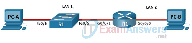
Device Names Table
You will receive one of three possible scenarios. In order to use the logical topology diagram that is provided with the instructions, use the device names in the Device Names Table.
| Topology Diagram Name | Your Scenario Name |
|---|---|
| R1 | R1 |
| S1 | S1 |
| PC-A | PC-A |
| PC-B | PC-B |
Addressing Requirements Table
| Item | Requirements |
|---|---|
| Network Address | 192.168.10.0/24 |
| LAN 1 subnet host requirements | 100 |
| LAN 2 subnet host requirements | 50 |
| R1 G0/0/1 | First host address in LAN 1 subnet |
| R1 G0/0/0 | First host address in LAN 2 subnet |
| S1 SVI | Second host address in LAN 1 subnet |
| PC-A | Last host address in LAN 1 subnet |
| PC-B | Last host address in LAN 2 subnet |
ITN Final PT Skills Assessment (PTSA)

A few things to keep in mind while completing this activity:
- Do not use the browser Back button or close or reload any exam windows during the exam.
- Do not close Packet Tracer when you are done. It will close automatically.
- Click the Submit Assessment button in the browser window to submit your work.
Assessment Objectives
- Part 1: Build the Network
- Part 2: Develop an IP Addressing Scheme
- Part 3: Configure Basic Device Settings
- Part 4: Configure Security Settings on R1 and S1
- Part 5: Configure the Hosts and Verify Connectivity
Instructions
In this assessment you will configure the R1 router and S1 switch, as you have done in the activities in this course. You will also connect two PCs using a switch and a router that are in the main wiring closet. You will subnet the 192.168.10.0/24 network to provide IPv4 addresses for two subnets that will support the required number of hosts. The larger subnet (LAN 1) requires 100 hosts and the smaller subnet (LAN 2) requires 50 hosts.
No subnet calculators may be used.
Part 1: Build the Network
a. Build the network according to the logical topology by placing the required equipment in the wiring closet equipment rack.
b. Cable the network devices in the closet as shown in the topology diagram.
c. Connect the hosts as shown in the topology diagram.
Part 2: Develop an IP Addressing Scheme
In this part of the assessment you will develop an IP addressing scheme. You will subnet an IPv4 network to create two subnets with the required number of hosts. You will also subnet an IPv6 network. You will then assign the addresses according to the requirements below.
Work with the following information:
- IPv4 Network: 192.168.10.0/24
- Required number of hosts in IPv4 LAN 1: 100
- Required number of hosts in IPv4 LAN 2: 50
a. Record your subnet assignments according to the following requirements.
1) Assign the first IPv4 address of each subnet to a router interface
- LAN 1 is hosted on R1 G0/0/1
- LAN 2 is hosted on R1 G0/0/0
2) Assign the last IPv4 address of each subnet to the PC NIC.
3) Assign the second IPv4 address of LAN 1 to S1 SVI.
Part 3: Configure Basic Device Settings
Network devices must be configured over a direct console connection.
Step 1: Configure Basic Settings
a. Disable DNS lookup on R1 and S1
b. Configure router hostname using the name R1.
c. Configure switch hostname using the name S1.
d. Configure an appropriate banner on R1 and S1.
e. Allow console logins with the password [email protected]!
Step 2: Configure Interfaces
a. Configure R1 G0/0/0 and G0/0/1 interfaces using the addressing from the previous part of this assessment:
- Interface description
- IPv4 address / subnet mask
b. Configure the S1 VLAN 1 SVI interface using the addressing from the previous part of this assessment:
- Interface description
- IPv4 address / subnet mask
- The switch should be reachable from devices on other networks.
Part 4: Configure Security Settings on R1 and S1
Step 1: Configure enhanced password security
a. Configure NoOneShouldKnow as the encrypted privileged EXEC password
b. Encrypt all plaintext passwords
c. Set minimum password length to 10 on R1.
Step 2: Configure SSH on R1 and S1
a. Configure netsec.com as the domain name
b. Configure a local user netadmin with the encrypted password Ci$co12345
c. Set login on vty lines to use local database.
d. Configure the vty lines to accept SSH access only.
e. Generate an RSA crypto key using 1024 bits modulus.
Step 3: Secure switch ports on S1
a. Shut down all unused ports on S1.
b. Enter descriptions for all unused switch ports to indicate that they are intentionally shutdown.
Part 5: Configure the Hosts and Verify Connectivity
Configure both hosts with the IPv4 addresses that were assigned in Part 2 of this assessment.
ID: 002
Answers Key – 100% Score
Part 1: Build the Network
Placing Switch S1 and Router R1 to wiring closet equipment rack.
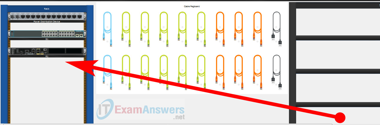
Using Copper Straight-Through cable to connect PC-A (FastEthernet0 port) and S1 (FastEthernet0/6 port)

Same as above, using Copper Straight-Through cable to connect all devices as shown in the topology diagram.
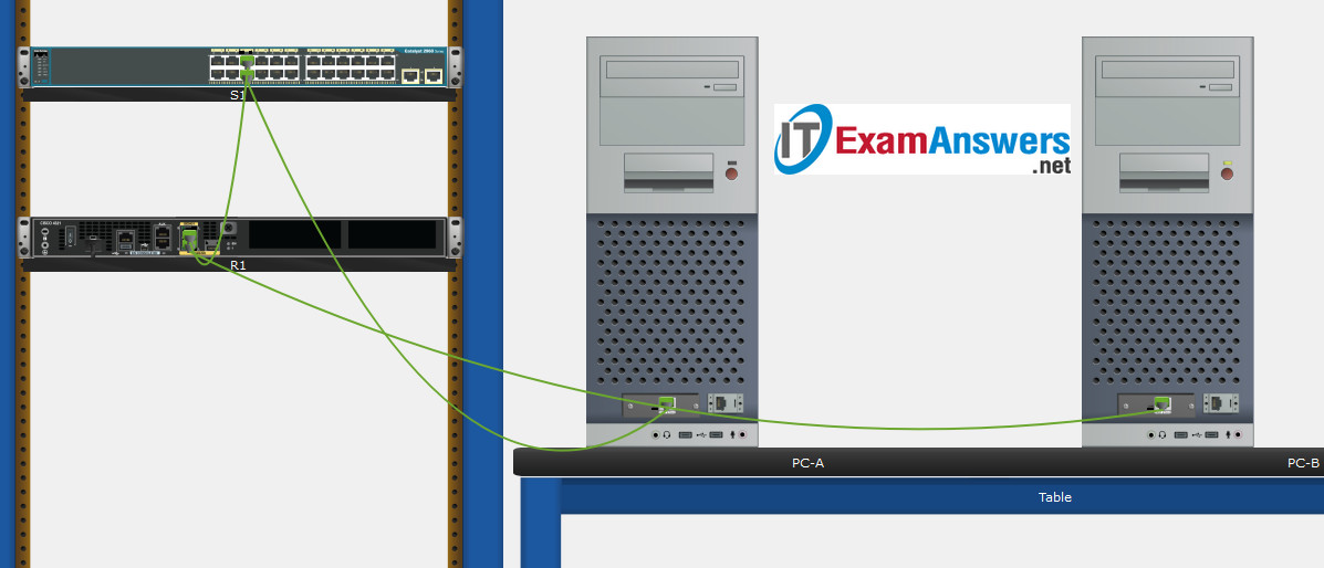
Turn-on PCs and Router R1

Part 2: Develop an IP Addressing Scheme
| Item | Requirements | IPv4 Address |
|---|---|---|
| Network Address | 192.168.10.0/24 | |
| LAN 1 subnet host requirements | 100 | 192.168.10.0/25 SM: 255.255.255.128 |
| LAN 2 subnet host requirements | 50 | 192.168.10.128/26 SM: 255.255.255.192 |
| R1 G0/0/1 | First host address in LAN 1 subnet | 192.168.10.1 |
| R1 G0/0/0 | First host address in LAN 2 subnet | 192.168.10.129 |
| S1 SVI | Second host address in LAN 1 subnet | 192.168.10.2 |
| PC-A | Last host address in LAN 1 subnet | 192.168.10.126 |
| PC-B | Last host address in LAN 2 subnet | 192.168.10.190 |
Configuration for router R1
Using line console to connect PC-A and Router R1
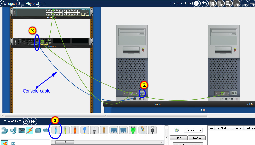
Click to PC-A –> Terminal app –> click OK
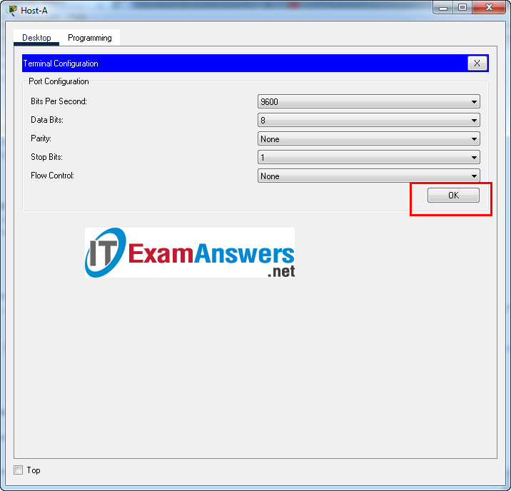
Router R1 configuration script
enable
configure terminal
no ip domain-lookup
hostname R1
banner motd #Unauthorized access to this device is prohibited!#

interface g0/0/0
description Connect to Subnet B
ip address 192.168.10.129 255.255.255.192
no shutdown
exit

interface g0/0/1
description Connect to Subnet A
ip address 192.168.10.1 255.255.255.128
no shutdown
exit

enable secret NoOneShouldKnow
service password-encryption
security passwords min-length 10

ip domain-name netsec.com
username netadmin secret Ci$co12345

line console 0
password [email protected]!
login
exit

line vty 0 15
transport input ssh
login local
exit

crypto key generate rsa
1024
exit
copy running-config startup-config
Configuration for Switch S1
Then, using Console cable to connect User-B and Switch
To show Console port on Switch, Right click Switch –> Inspect Rear –> Console port

Switch S1 configuration script
enable
configure terminal
no ip domain-lookup
hostname S1
banner motd #Unauthorized access to this device is prohibited!#

interface vlan 1
description Switch Subnet A
ip address 192.168.10.2 255.255.255.128
no shutdown
exit

ip default-gateway 192.168.10.1

enable secret NoOneShouldKnow
service password-encryption

ip domain-name netsec.com
username netadmin secret Ci$co12345

line console 0
password [email protected]!
login
exit

line vty 0 15
transport input ssh
login local
exit

crypto key generate rsa
1024

int range f0/1 - 4, f0/7 - 24, g0/1 - 2
description Unused switch ports
shutdown

end
copy running-config startup-config
Part 5: Configure the Hosts and Verify Connectivity
On PCs, go to Desktop tab –> IP Configuration menu
| PC-A Network Configuration | |
|---|---|
| IPv4 Address | 192.168.10.126 |
| Subnet Mask | 255.255.255.128 |
| IPv4 Default Gateway | 192.168.10.1 |

| PC-B Network Configuration | |
|---|---|
| IPv4 Address | 192.168.10.190 |
| Subnet Mask | 255.255.255.192 |
| IPv4 Default Gateway | 192.168.10.129 |

Download PDF & Packet Tracer files:
[sociallocker id=”57850″][wpdm_package id=’65255′][/sociallocker]
ITN Final Skills Exam (PTSA)
ITN (Version 7.00) Final PT Skills Assessment (PTSA) Exam Answers
Topology
Device Names Table
You will receive one of three possible scenarios. In order to use the logical topology diagram that is provided with the instructions, use the device names in the Device Names Table.
| Topology Diagram Name | Your Scenario Name |
|---|---|
| R1 | Central-RT |
| S1 | Central-SW |
| PC-A | User-A |
| PC-B | User-B |
Addressing Requirements Table
| Item | Requirements |
|---|---|
| Network Address | 192.168.10.0/24 |
| LAN 1 subnet host requirements | 100 |
| LAN 2 subnet host requirements | 50 |
| Central-RT G0/0/1 | First host address in LAN 1 subnet |
| Central-RT G0/0/0 | First host address in LAN 2 subnet |
| Central-SW SVI | Second host address in LAN 1 subnet |
| User-A | Last host address in LAN 1 subnet |
| User-B | Last host address in LAN 2 subnet |
ITN Final PT Skills Assessment (PTSA)
A few things to keep in mind while completing this activity:
- Do not use the browser Back button or close or reload any exam windows during the exam.
- Do not close Packet Tracer when you are done. It will close automatically.
- Click the Submit Assessment button in the browser window to submit your work.
Assessment Objectives
- Part 1: Build the Network
- Part 2: Develop an IP Addressing Scheme
- Part 3: Configure Basic Device Settings
- Part 4: Configure Security Settings on Central-RT and Central-SW
- Part 5: Configure the Hosts and Verify Connectivity
Instructions
In this assessment you will configure the Central-RT router and Central-SW switch, as you have done in the activities in this course. You will also connect two PCs using a switch and a router that are in the main wiring closet. You will subnet the 192.168.10.0/24 network to provide IPv4 addresses for two subnets that will support the required number of hosts. The larger subnet (LAN 1) requires 100 hosts and the smaller subnet (LAN 2) requires 50 hosts.
No subnet calculators may be used.
Part 1: Build the Network
a. Build the network according to the logical topology by placing the required equipment in the wiring closet equipment rack.
b. Cable the network devices in the closet as shown in the topology diagram.
c. Connect the hosts as shown in the topology diagram.
Part 2: Develop an IP Addressing Scheme
In this part of the assessment you will develop an IP addressing scheme. You will subnet an IPv4 network to create two subnets with the required number of hosts. You will also subnet an IPv6 network. You will then assign the addresses according to the requirements below.
Work with the following information:
- IPv4 Network: 192.168.10.0/24
- Required number of hosts in IPv4 LAN 1: 100
- Required number of hosts in IPv4 LAN 2: 50
a. Record your subnet assignments according to the following requirements.
1) Assign the first IPv4 address of each subnet to a router interface
- LAN 1 is hosted on Central-RT G0/0/1
- LAN 2 is hosted on Central-RT G0/0/0
2) Assign the last IPv4 address of each subnet to the PC NIC.
3) Assign the second IPv4 address of LAN 1 to Central-SW SVI.
Part 3: Configure Basic Device Settings
Network devices must be configured over a direct console connection.
Step 1: Configure Basic Settings
a. Disable DNS lookup on Central-RT and Central-SW
b. Configure router hostname using the name Central-RT.
c. Configure switch hostname using the name Central-SW.
d. Configure an appropriate banner on Central-RT and Central-SW.
e. Allow console logins with the password [email protected]!
Step 2: Configure Interfaces
a. Configure Central-RT G0/0/0 and G0/0/1 interfaces using the addressing from the previous part of this assessment:
- Interface description
- IPv4 address / subnet mask
b. Configure the Central-SW VLAN 1 SVI interface using the addressing from the previous part of this assessment:
- Interface description
- IPv4 address / subnet mask
- The switch should be reachable from devices on other networks.
Part 4: Configure Security Settings on Central-RT and Central-SW
Step 1: Configure enhanced password security
a. Configure NoOneShouldKnow as the encrypted privileged EXEC password
b. Encrypt all plaintext passwords
c. Set minimum password length to 10 on Central-RT.
Step 2: Configure SSH on Central-RT and Central-SW
a. Configure netsec.com as the domain name
b. Configure a local user netadmin with the encrypted password Ci$co12345
c. Set login on vty lines to use local database.
d. Configure the vty lines to accept SSH access only.
e. Generate an RSA crypto key using 1024 bits modulus.
Step 3: Secure switch ports on Central-SW
a. Shut down all unused ports on Central-SW.
b. Enter descriptions for all unused switch ports to indicate that they are intentionally shutdown.
Part 5: Configure the Hosts and Verify Connectivity
Configure both hosts with the IPv4 addresses that were assigned in Part 2 of this assessment.
ID: 012
Answers Key
Part 1: Build the Network
Placing Switch Central-SW and Router Central-RT to wiring closet equipment rack.
Using Copper Straight-Through cable to connect User-A (FastEthernet0 port) and Central-SW (FastEthernet0/6 port)
Same as above, using Copper Straight-Through cable to connect all devices as shown in the topology diagram.
Turn-on PCs and Router Central-RT
Part 2: Develop an IP Addressing Scheme
| Item | Requirements | IPv4 Address |
|---|---|---|
| Network Address | 192.168.10.0/24 | |
| LAN 1 subnet host requirements | 100 | 192.168.10.0/25 SM: 255.255.255.128 |
| LAN 2 subnet host requirements | 50 | 192.168.10.128/26 SM: 255.255.255.192 |
| Central-RT G0/0/1 | First host address in LAN 1 subnet | 192.168.10.1 |
| Central-RT G0/0/0 | First host address in LAN 2 subnet | 192.168.10.129 |
| Central-SW SVI | Second host address in LAN 1 subnet | 192.168.10.2 |
| User-A | Last host address in LAN 1 subnet | 192.168.10.126 |
| User-B | Last host address in LAN 2 subnet | 192.168.10.190 |
Using line console to connect User-A and Router
Click to User-A –> Terminal app –> click OK
Router Central-RT configuration script
enable
configure terminal
no ip domain-lookup
hostname Central-RT
banner motd #Unauthorized access to this device is prohibited!#

interface g0/0/0
description Connect to Subnet B
ip address 192.168.10.129 255.255.255.192
no shutdown
exit

interface g0/0/1
description Connect to Subnet A
ip address 192.168.10.1 255.255.255.128
no shutdown
exit

enable secret NoOneShouldKnow
service password-encryption
security passwords min-length 10

ip domain-name netsec.com
username netadmin secret Ci$co12345

line console 0
password [email protected]!
login
exit

line vty 0 15
transport input ssh
login local
exit

crypto key generate rsa
1024
exit
copy running-config startup-config
Configuration for Switch Central-SW
Then, using Console cable to connect User-B and Switch
To show Console port on Switch, Right click Switch –> Inspect Rear –> Console port
Switch Central-SW configuration script
enable
configure terminal
no ip domain-lookup
hostname Central-SW
banner motd #Unauthorized access to this device is prohibited!#

interface vlan 1
description Switch Subnet A
ip address 192.168.10.2 255.255.255.128
no shutdown
exit

ip default-gateway 192.168.10.1

enable secret NoOneShouldKnow
service password-encryption

ip domain-name netsec.com
username netadmin secret Ci$co12345

line console 0
password [email protected]!
login
exit

line vty 0 15
transport input ssh
login local
exit

crypto key generate rsa
1024

int range f0/1 - 4, f0/7 - 24, g0/1 - 2
description Unused switch ports
shutdown

end
copy running-config startup-config
Part 5: Configure the Hosts and Verify Connectivity
On PCs, go to Desktop tab –> IP Configuration menu
| PC-A Network Configuration | |
|---|---|
| IPv4 Address | 192.168.10.126 |
| Subnet Mask | 255.255.255.128 |
| IPv4 Default Gateway | 192.168.10.1 |
| PC-B Network Configuration | |
|---|---|
| IPv4 Address | 192.168.10.190 |
| Subnet Mask | 255.255.255.192 |
| IPv4 Default Gateway | 192.168.10.129 |
Download PDF & Packet Tracer files:
[sociallocker id=”57850″][wpdm_package id=’65255′][/sociallocker]
ITN Final Skills Exam (PTSA)
ITN (Version 7.00) Final PT Skills Assessment (PTSA) Exam Answers
Topology
Device Names Table
You will receive one of three possible scenarios. In order to use the logical topology diagram that is provided with the instructions, use the device names in the Device Names Table.
| Topology Diagram Name | Your Scenario Name |
|---|---|
| R1 | Central-RT |
| S1 | Central-SW |
| PC-A | User-A |
| PC-B | User-B |
Addressing Requirements Table
| Item | Requirements |
|---|---|
| Network Address | 209.165.201.0/24 |
| LAN 1 subnet host requirements | 29 |
| LAN 2 subnet host requirements | 17 |
| Central-RT G0/0/1 | First host address in LAN 1 subnet |
| Central-RT G0/0/0 | First host address in LAN 2 subnet |
| Central-SW SVI | Second host address in LAN 1 subnet |
| User-A | Last host address in LAN 1 subnet |
| User-B | Last host address in LAN 2 subnet |
ITN Final PT Skills Assessment (PTSA)
A few things to keep in mind while completing this activity:
- Do not use the browser Back button or close or reload any exam windows during the exam.
- Do not close Packet Tracer when you are done. It will close automatically.
- Click the Submit Assessment button in the browser window to submit your work.
Assessment Objectives
- Part 1: Build the Network
- Part 2: Develop an IP Addressing Scheme
- Part 3: Configure Basic Device Settings
- Part 4: Configure Security Settings on Central-RT and Central-SW
- Part 5: Configure the Hosts and Verify Connectivity
Instructions
In this assessment you will configure the Central-RT router and Central-SW switch, as you have done in the activities in this course. You will also connect two PCs using a switch and a router that are in the main wiring closet. You will subnet the 209.165.201.0/24 network to provide IPv4 addresses for two subnets that will support the required number of hosts. The larger subnet (LAN 1) requires 29 hosts and the smaller subnet (LAN 2) requires 17 hosts.
No subnet calculators may be used.
Part 1: Build the Network
a. Build the network according to the logical topology by placing the required equipment in the wiring closet equipment rack.
b. Cable the network devices in the closet as shown in the topology diagram.
c. Connect the hosts as shown in the topology diagram.
Part 2: Develop an IP Addressing Scheme
In this part of the assessment you will develop an IP addressing scheme. You will subnet an IPv4 network to create two subnets with the required number of hosts. You will also subnet an IPv6 network. You will then assign the addresses according to the requirements below.
Work with the following information:
- IPv4 Network: 209.165.201.0/24
- Required number of hosts in IPv4 LAN 1: 29
- Required number of hosts in IPv4 LAN 2: 17
a. Record your subnet assignments according to the following requirements.
1) Assign the first IPv4 address of each subnet to a router interface
- LAN 1 is hosted on Central-RT G0/0/1
- LAN 2 is hosted on Central-RT G0/0/0
2) Assign the last IPv4 address of each subnet to the PC NIC.
3) Assign the second IPv4 address of LAN 1 to Central-SW SVI.
Part 3: Configure Basic Device Settings
Network devices must be configured over a direct console connection.
Step 1: Configure Basic Settings
a. Disable DNS lookup on Central-RT and Central-SW
b. Configure router hostname using the name Central-RT.
c. Configure switch hostname using the name Central-SW.
d. Configure an appropriate banner on Central-RT and Central-SW.
e. Allow console logins with the password [email protected]!
Step 2: Configure Interfaces
a. Configure Central-RT G0/0/0 and G0/0/1 interfaces using the addressing from the previous part of this assessment:
- Interface description
- IPv4 address / subnet mask
b. Configure the Central-SW VLAN 1 SVI interface using the addressing from the previous part of this assessment:
- Interface description
- IPv4 address / subnet mask
- The switch should be reachable from devices on other networks.
Part 4: Configure Security Settings on Central-RT and Central-SW
Step 1: Configure enhanced password security
a. Configure NoOneShouldKnow as the encrypted privileged EXEC password
b. Encrypt all plaintext passwords
c. Set minimum password length to 10 on Central-RT.
Step 2: Configure SSH on Central-RT and Central-SW
a. Configure netsec.com as the domain name
b. Configure a local user netadmin with the encrypted password Ci$co12345
c. Set login on vty lines to use local database.
d. Configure the vty lines to accept SSH access only.
e. Generate an RSA crypto key using 1024 bits modulus.
Step 3: Secure switch ports on Central-SW
a. Shut down all unused ports on Central-SW.
b. Enter descriptions for all unused switch ports to indicate that they are intentionally shutdown.
Part 5: Configure the Hosts and Verify Connectivity
Configure both hosts with the IPv4 addresses that were assigned in Part 2 of this assessment.
ID: 211
Answers Key – 100% Score
Part 1: Build the Network
Placing Switch Central-SW and Router Central-RT to wiring closet equipment rack.
Using Copper Straight-Through cable to connect User-A (FastEthernet0 port) and Central-SW (FastEthernet0/6 port)
Same as above, using Copper Straight-Through cable to connect all devices as shown in the topology diagram.
Turn-on PCs and Router Central-RT
Part 2: Develop an IP Addressing Scheme
| Item | Requirements | IPv4 Address |
|---|---|---|
| Network Address | 209.165.201.0/24 | |
| LAN 1 subnet host requirements | 29 | 209.165.201.0/27 SM: 255.255.255.224 |
| LAN 2 subnet host requirements | 17 | 209.165.201.32/27 SM: 255.255.255.224 |
| Central-RT G0/0/1 | First host address in LAN 1 subnet | 209.165.201.1 |
| Central-RT G0/0/0 | First host address in LAN 2 subnet | 209.165.201.33 |
| Central-SW SVI | Second host address in LAN 1 subnet | 209.165.201.2 |
| User-A | Last host address in LAN 1 subnet | 209.165.201.30 |
| User-B | Last host address in LAN 2 subnet | 209.165.201.62 |
Using line console to connect User-A and Router
Click to User-A –> Terminal app –> click OK
Router Central-RT configuration script
enable
configure terminal
no ip domain-lookup
hostname Central-RT
banner motd #Unauthorized access to this device is prohibited!#

interface g0/0/0
description Connect to Subnet B
ip address 209.165.201.33 255.255.255.224
no shutdown
exit

interface g0/0/1
description Connect to Subnet A
ip address 209.165.201.1 255.255.255.224
no shutdown
exit

enable secret NoOneShouldKnow
service password-encryption
security passwords min-length 10

ip domain-name netsec.com
username netadmin secret Ci$co12345

line console 0
password [email protected]!
login
exit

line vty 0 15
transport input ssh
login local
exit

crypto key generate rsa
1024
exit
copy running-config startup-config
Configuration for Switch Central-SW
Then, using Console cable to connect User-B and Switch
To show Console port on Switch, Right click Switch –> Inspect Rear –> Console port
Switch Central-SW configuration script
enable
configure terminal
no ip domain-lookup
hostname Central-SW
banner motd #Unauthorized access to this device is prohibited!#

interface vlan 1
description Switch Subnet A
ip address 209.165.201.2 255.255.255.224
no shutdown
exit

ip default-gateway 209.165.201.1

enable secret NoOneShouldKnow
service password-encryption

ip domain-name netsec.com
username netadmin secret Ci$co12345

line console 0
password [email protected]!
login
exit

line vty 0 15
transport input ssh
login local
exit

crypto key generate rsa
1024

int range f0/1 - 4, f0/7 - 24, g0/1 - 2
description Unused switch ports
shutdown

end
copy running-config startup-config
Part 5: Configure the Hosts and Verify Connectivity
On PCs, go to Desktop tab –> IP Configuration menu
| PC-A Network Configuration | |
|---|---|
| IPv4 Address | 209.165.201.30 |
| Subnet Mask | 255.255.255.224 |
| IPv4 Default Gateway | 209.165.201.1 |
| PC-B Network Configuration | |
|---|---|
| IPv4 Address | 209.165.201.62 |
| Subnet Mask | 255.255.255.224 |
| IPv4 Default Gateway | 209.165.201.33 |
Download PDF & Packet Tracer files:
[sociallocker id=”57850″][wpdm_package id=’65255′][/sociallocker]
ITN Final Skills Exam (PTSA)
ITN (Version 7.00) Final PT Skills Assessment (PTSA) Exam Answers
Topology
Device Names Table
You will receive one of three possible scenarios. In order to use the logical topology diagram that is provided with the instructions, use the device names in the Device Names Table.
| Topology Diagram Name | Your Scenario Name |
|---|---|
| R1 | Router-A |
| S1 | Switch-A |
| PC-A | Host-A |
| PC-B | Host-B |
Addressing Requirements Table
| Item | Requirements |
|---|---|
| Network Address | 172.16.1.0/24 |
| LAN 1 subnet host requirements | 60 |
| LAN 2 subnet host requirements | 20 |
| Router-A G0/0/1 | First host address in LAN 1 subnet |
| Router-A G0/0/0 | First host address in LAN 2 subnet |
| Switch-A SVI | Second host address in LAN 1 subnet |
| User-A | Last host address in LAN 1 subnet |
| User-B | Last host address in LAN 2 subnet |
ITN Final PT Skills Assessment (PTSA)
A few things to keep in mind while completing this activity:
- Do not use the browser Back button or close or reload any exam windows during the exam.
- Do not close Packet Tracer when you are done. It will close automatically.
- Click the Submit Assessment button in the browser window to submit your work.
Assessment Objectives
- Part 1: Build the Network
- Part 2: Develop an IP Addressing Scheme
- Part 3: Configure Basic Device Settings
- Part 4: Configure Security Settings on Router-A and Switch-A
- Part 5: Configure the Hosts and Verify Connectivity
Instructions
In this assessment you will configure the Router-A router and Switch-A switch, as you have done in the activities in this course. You will also connect two PCs using a switch and a router that are in the main wiring closet. You will subnet the 172.16.1.0/24 network to provide IPv4 addresses for two subnets that will support the required number of hosts. The larger subnet (LAN 1) requires 60 hosts and the smaller subnet (LAN 2) requires 20 hosts.
No subnet calculators may be used.
Part 1: Build the Network
a. Build the network according to the logical topology by placing the required equipment in the wiring closet equipment rack.
b. Cable the network devices in the closet as shown in the topology diagram.
c. Connect the hosts as shown in the topology diagram.
Part 2: Develop an IP Addressing Scheme
In this part of the assessment you will develop an IP addressing scheme. You will subnet an IPv4 network to create two subnets with the required number of hosts. You will also subnet an IPv6 network. You will then assign the addresses according to the requirements below.
Work with the following information:
- IPv4 Network: 172.16.1.0/24
- Required number of hosts in IPv4 LAN 1: 60
- Required number of hosts in IPv4 LAN 2: 20
a. Record your subnet assignments according to the following requirements.
1) Assign the first IPv4 address of each subnet to a router interface
- LAN 1 is hosted on Router-A G0/0/1
- LAN 2 is hosted on Router-A G0/0/0
2) Assign the last IPv4 address of each subnet to the PC NIC.
3) Assign the second IPv4 address of LAN 1 to Switch-A SVI.
Part 3: Configure Basic Device Settings
Network devices must be configured over a direct console connection.
Step 1: Configure Basic Settings
a. Disable DNS lookup on Router-A and Switch-A
b. Configure router hostname using the name Router-A.
c. Configure switch hostname using the name Switch-A.
d. Configure an appropriate banner on Router-A and Switch-A.
e. Allow console logins with the password [email protected]!
Step 2: Configure Interfaces
a. Configure Router-A G0/0/0 and G0/0/1 interfaces using the addressing from the previous part of this assessment:
- Interface description
- IPv4 address / subnet mask
b. Configure the Switch-A VLAN 1 SVI interface using the addressing from the previous part of this assessment:
- Interface description
- IPv4 address / subnet mask
- The switch should be reachable from devices on other networks.
Part 4: Configure Security Settings on Router-A and Switch-A
Step 1: Configure enhanced password security
a. Configure NoOneShouldKnow as the encrypted privileged EXEC password
b. Encrypt all plaintext passwords
c. Set minimum password length to 10 on Router-A.
Step 2: Configure SSH on Router-A and Switch-A
a. Configure netsec.com as the domain name
b. Configure a local user netadmin with the encrypted password Ci$co12345
c. Set login on vty lines to use local database.
d. Configure the vty lines to accept SSH access only.
e. Generate an RSA crypto key using 1024 bits modulus.
Step 3: Secure switch ports on Switch-A
a. Shut down all unused ports on Switch-A.
b. Enter descriptions for all unused switch ports to indicate that they are intentionally shutdown.
Part 5: Configure the Hosts and Verify Connectivity
Configure both hosts with the IPv4 addresses that were assigned in Part 2 of this assessment.
ID: 120
Answers Key – 100% Score
Part 1: Build the Network
Placing Switch Switch-A and Router Router-A to wiring closet equipment rack.
Using Copper Straight-Through cable to connect User-A (FastEthernet0 port) and Switch-A (FastEthernet0/6 port)
Same as above, using Copper Straight-Through cable to connect all devices as shown in the topology diagram.
Turn-on PCs and Router Router-A
Part 2: Develop an IP Addressing Scheme
| Item | Requirements | IPv4 Address |
|---|---|---|
| Network Address | 172.16.1.0/24 | |
| LAN 1 subnet host requirements | 60 | 172.16.1.0/26 SM: 255.255.255.192 |
| LAN 2 subnet host requirements | 20 | 172.16.1.64/27 SM: 255.255.255.224 |
| Router-A G0/0/1 | First host address in LAN 1 subnet | 172.16.1.1 |
| Router-A G0/0/0 | First host address in LAN 2 subnet | 172.16.1.65 |
| Switch-A SVI | Second host address in LAN 1 subnet | 172.16.1.2 |
| User-A | Last host address in LAN 1 subnet | 172.16.1.62 |
| User-B | Last host address in LAN 2 subnet | 172.16.1.94 |
Using line console to connect User-A and Router
Click to User-A –> Terminal app –> click OK
Router Router-A configuration script
enable
configure terminal
no ip domain-lookup
hostname Router-A
banner motd #Unauthorized access to this device is prohibited!#

interface g0/0/0
description Connect to Subnet B
ip address 172.16.1.65 255.255.255.224
no shutdown
exit

interface g0/0/1
description Connect to Subnet A
ip address 172.16.1.1 255.255.255.192
no shutdown
exit

enable secret NoOneShouldKnow
service password-encryption
security passwords min-length 10

ip domain-name netsec.com
username netadmin secret Ci$co12345

line console 0
password [email protected]!
login
exit

line vty 0 15
transport input ssh
login local
exit

crypto key generate rsa
1024
exit
copy running-config startup-config
Configuration for Switch-A
Then, using Console cable to connect User-B and Switch
To show Console port on Switch, Right click Switch –> Inspect Rear –> Console port
Switch Switch-A configuration script
enable
configure terminal
no ip domain-lookup
hostname Switch-A
banner motd #Unauthorized access to this device is prohibited!#

interface vlan 1
description Switch Subnet A
ip address 172.16.1.2 255.255.255.192
no shutdown
exit

ip default-gateway 172.16.1.1

enable secret NoOneShouldKnow
service password-encryption

ip domain-name netsec.com
username netadmin secret Ci$co12345

line console 0
password [email protected]!
login
exit

line vty 0 15
transport input ssh
login local
exit

crypto key generate rsa
1024

int range f0/1 - 4, f0/7 - 24, g0/1 - 2
description Unused switch ports
shutdown

end
copy running-config startup-config
Part 5: Configure the Hosts and Verify Connectivity
On PCs, go to Desktop tab –> IP Configuration menu
| PC-A Network Configuration | |
|---|---|
| IPv4 Address | 172.16.1.62 |
| Subnet Mask | 255.255.255.192 |
| IPv4 Default Gateway | 172.16.1.1 |
| PC-B Network Configuration | |
|---|---|
| IPv4 Address | 172.16.1.94 |
| Subnet Mask | 255.255.255.224 |
| IPv4 Default Gateway | 172.16.1.65 |
Download PDF & Packet Tracer files:
[sociallocker id=”57850″][wpdm_package id=’65255′][/sociallocker]
ITN Final Skills Exam (PTSA)
ITN (Version 7.00) Final PT Skills Assessment (PTSA) Exam Answers
Topology
Device Names Table
You will receive one of three possible scenarios. In order to use the logical topology diagram that is provided with the instructions, use the device names in the Device Names Table.
| Topology Diagram Name | Your Scenario Name |
|---|---|
| R1 | Central-RT |
| S1 | Central-SW |
| PC-A | User-A |
| PC-B | User-B |
Addressing Requirements Table
| Item | Requirements |
|---|---|
| Network Address | 192.168.10.0/24 |
| LAN 1 subnet host requirements | 100 |
| LAN 2 subnet host requirements | 50 |
| Central-RT G0/0/1 | First host address in LAN 1 subnet |
| Central-RT G0/0/0 | First host address in LAN 2 subnet |
| Central-SW SVI | Second host address in LAN 1 subnet |
| User-A | Last host address in LAN 1 subnet |
| User-B | Last host address in LAN 2 subnet |
ITN Final PT Skills Assessment (PTSA)
A few things to keep in mind while completing this activity:
- Do not use the browser Back button or close or reload any exam windows during the exam.
- Do not close Packet Tracer when you are done. It will close automatically.
- Click the Submit Assessment button in the browser window to submit your work.
Assessment Objectives
- Part 1: Build the Network
- Part 2: Develop an IP Addressing Scheme
- Part 3: Configure Basic Device Settings
- Part 4: Configure Security Settings on Central-RT and Central-SW
- Part 5: Configure the Hosts and Verify Connectivity
Instructions
In this assessment you will configure the Central-RT router and Central-SW switch, as you have done in the activities in this course. You will also connect two PCs using a switch and a router that are in the main wiring closet. You will subnet the 192.168.10.0/24 network to provide IPv4 addresses for two subnets that will support the required number of hosts. The larger subnet (LAN 1) requires 100 hosts and the smaller subnet (LAN 2) requires 50 hosts.
No subnet calculators may be used.
Part 1: Build the Network
a. Build the network according to the logical topology by placing the required equipment in the wiring closet equipment rack.
b. Cable the network devices in the closet as shown in the topology diagram.
c. Connect the hosts as shown in the topology diagram.
Part 2: Develop an IP Addressing Scheme
In this part of the assessment you will develop an IP addressing scheme. You will subnet an IPv4 network to create two subnets with the required number of hosts. You will also subnet an IPv6 network. You will then assign the addresses according to the requirements below.
Work with the following information:
- IPv4 Network: 192.168.10.0/24
- Required number of hosts in IPv4 LAN 1: 100
- Required number of hosts in IPv4 LAN 2: 50
a. Record your subnet assignments according to the following requirements.
1) Assign the first IPv4 address of each subnet to a router interface
- LAN 1 is hosted on Central-RT G0/0/1
- LAN 2 is hosted on Central-RT G0/0/0
2) Assign the last IPv4 address of each subnet to the PC NIC.
3) Assign the second IPv4 address of LAN 1 to Central-SW SVI.
Part 3: Configure Basic Device Settings
Network devices must be configured over a direct console connection.
Step 1: Configure Basic Settings
a. Disable DNS lookup on Central-RT and Central-SW
b. Configure router hostname using the name Central-RT.
c. Configure switch hostname using the name Central-SW.
d. Configure an appropriate banner on Central-RT and Central-SW.
e. Allow console logins with the password [email protected]!
Step 2: Configure Interfaces
a. Configure Central-RT G0/0/0 and G0/0/1 interfaces using the addressing from the previous part of this assessment:
- Interface description
- IPv4 address / subnet mask
b. Configure the Central-SW VLAN 1 SVI interface using the addressing from the previous part of this assessment:
- Interface description
- IPv4 address / subnet mask
- The switch should be reachable from devices on other networks.
Part 4: Configure Security Settings on Central-RT and Central-SW
Step 1: Configure enhanced password security
a. Configure DontTellAnyone as the encrypted privileged EXEC password
b. Encrypt all plaintext passwords
c. Set minimum password length to 10 on Central-RT.
Step 2: Configure SSH on Central-RT and Central-SW
a. Configure netsec.com as the domain name
b. Configure a local user netadmin with the encrypted password Ci$co12345
c. Set login on vty lines to use local database.
d. Configure the vty lines to accept SSH access only.
e. Generate an RSA crypto key using 1024 bits modulus.
Step 3: Secure switch ports on Central-SW
a. Shut down all unused ports on Central-SW.
b. Enter descriptions for all unused switch ports to indicate that they are intentionally shutdown.
Part 5: Configure the Hosts and Verify Connectivity
Configure both hosts with the IPv4 addresses that were assigned in Part 2 of this assessment.
ID: 011
Answers Key
Part 1: Build the Network
Placing Switch Central-SW and Router Central-RT to wiring closet equipment rack.
Using Copper Straight-Through cable to connect User-A (FastEthernet0 port) and Central-SW (FastEthernet0/6 port)
Same as above, using Copper Straight-Through cable to connect all devices as shown in the topology diagram.
Turn-on PCs and Router Central-RT
Part 2: Develop an IP Addressing Scheme
| Item | Requirements | IPv4 Address |
|---|---|---|
| Network Address | 192.168.10.0/24 | |
| LAN 1 subnet host requirements | 100 | 192.168.10.0/25 SM: 255.255.255.128 |
| LAN 2 subnet host requirements | 50 | 192.168.10.128/26 SM: 255.255.255.192 |
| Central-RT G0/0/1 | First host address in LAN 1 subnet | 192.168.10.1 |
| Central-RT G0/0/0 | First host address in LAN 2 subnet | 192.168.10.129 |
| Central-SW SVI | Second host address in LAN 1 subnet | 192.168.10.2 |
| User-A | Last host address in LAN 1 subnet | 192.168.10.126 |
| User-B | Last host address in LAN 2 subnet | 192.168.10.190 |
Using line console to connect User-A and Router
Click to User-A –> Terminal app –> click OK
Router Central-RT configuration script
enable
configure terminal
no ip domain-lookup
hostname Central-RT
banner motd #Unauthorized access to this device is prohibited!#

interface g0/0/0
description Connect to Subnet B
ip address 192.168.10.129 255.255.255.192
no shutdown
exit

interface g0/0/1
description Connect to Subnet A
ip address 192.168.10.1 255.255.255.128
no shutdown
exit

enable secret DontTellAnyone
service password-encryption
security passwords min-length 10

ip domain-name netsec.com
username netadmin secret Ci$co12345

line console 0
password [email protected]!
login
exit

line vty 0 15
transport input ssh
login local
exit

crypto key generate rsa
1024
exit
copy running-config startup-config
Configuration for Switch Central-SW
Then, using Console cable to connect User-B and Switch
To show Console port on Switch, Right click Switch –> Inspect Rear –> Console port
Switch Central-SW configuration script
enable
configure terminal
no ip domain-lookup
hostname Central-SW
banner motd #Unauthorized access to this device is prohibited!#

interface vlan 1
description Switch Subnet A
ip address 192.168.10.2 255.255.255.128
no shutdown
exit

ip default-gateway 192.168.10.1

enable secret DontTellAnyone
service password-encryption

ip domain-name netsec.com
username netadmin secret Ci$co12345

line console 0
password [email protected]!
login
exit

line vty 0 15
transport input ssh
login local
exit

crypto key generate rsa
1024

int range f0/1 - 4, f0/7 - 24, g0/1 - 2
description Unused switch ports
shutdown

end
copy running-config startup-config
Part 5: Configure the Hosts and Verify Connectivity
On PCs, go to Desktop tab –> IP Configuration menu
| PC-A Network Configuration | |
|---|---|
| IPv4 Address | 192.168.10.126 |
| Subnet Mask | 255.255.255.128 |
| IPv4 Default Gateway | 192.168.10.1 |
| PC-B Network Configuration | |
|---|---|
| IPv4 Address | 192.168.10.190 |
| Subnet Mask | 255.255.255.192 |
| IPv4 Default Gateway | 192.168.10.129 |
Download PDF & Packet Tracer files:
[sociallocker id=”57850″][wpdm_package id=’65255′][/sociallocker]
ITN Final Skills Exam (PTSA)
ITN (Version 7.00) Final PT Skills Assessment (PTSA) Exam Answers
Topology
Device Names Table
You will receive one of three possible scenarios. In order to use the logical topology diagram that is provided with the instructions, use the device names in the Device Names Table.
| Topology Diagram Name | Your Scenario Name |
|---|---|
| R1 | Router-A |
| S1 | Switch-A |
| PC-A | Host-A |
| PC-B | Host-B |
Addressing Requirements Table
| Item | Requirements |
|---|---|
| Network Address | 192.168.10.0/24 |
| LAN 1 subnet host requirements | 100 |
| LAN 2 subnet host requirements | 50 |
| Router-A G0/0/1 | First host address in LAN 1 subnet |
| Router-A G0/0/0 | First host address in LAN 2 subnet |
| Switch-A SVI | Second host address in LAN 1 subnet |
| Host-A | Last host address in LAN 1 subnet |
| Host-B | Last host address in LAN 2 subnet |
ITN Final PT Skills Assessment (PTSA)
A few things to keep in mind while completing this activity:
- Do not use the browser Back button or close or reload any exam windows during the exam.
- Do not close Packet Tracer when you are done. It will close automatically.
- Click the Submit Assessment button in the browser window to submit your work.
Assessment Objectives
- Part 1: Build the Network
- Part 2: Develop an IP Addressing Scheme
- Part 3: Configure Basic Device Settings
- Part 4: Configure Security Settings on Router-A and Switch-A
- Part 5: Configure the Hosts and Verify Connectivity
Instructions
In this assessment you will configure the Router-A router and Switch-A switch, as you have done in the activities in this course. You will also connect two PCs using a switch and a router that are in the main wiring closet. You will subnet the 192.168.10.0/24 network to provide IPv4 addresses for two subnets that will support the required number of hosts. The larger subnet (LAN 1) requires 100 hosts and the smaller subnet (LAN 2) requires 50 hosts.
No subnet calculators may be used.
Part 1: Build the Network
a. Build the network according to the logical topology by placing the required equipment in the wiring closet equipment rack.
b. Cable the network devices in the closet as shown in the topology diagram.
c. Connect the hosts as shown in the topology diagram.
Part 2: Develop an IP Addressing Scheme
In this part of the assessment you will develop an IP addressing scheme. You will subnet an IPv4 network to create two subnets with the required number of hosts. You will also subnet an IPv6 network. You will then assign the addresses according to the requirements below.
Work with the following information:
- IPv4 Network: 192.168.10.0/24
- Required number of hosts in IPv4 LAN 1: 100
- Required number of hosts in IPv4 LAN 2: 50
a. Record your subnet assignments according to the following requirements.
1) Assign the first IPv4 address of each subnet to a router interface
- LAN 1 is hosted on Router-A G0/0/1
- LAN 2 is hosted on Router-A G0/0/0
2) Assign the last IPv4 address of each subnet to the PC NIC.
3) Assign the second IPv4 address of LAN 1 to Switch-A SVI.
Part 3: Configure Basic Device Settings
Network devices must be configured over a direct console connection.
Step 1: Configure Basic Settings
a. Disable DNS lookup on Router-A and Switch-A
b. Configure router hostname using the name Router-A.
c. Configure switch hostname using the name Switch-A.
d. Configure an appropriate banner on Router-A and Switch-A.
e. Allow console logins with the password [email protected]!
Step 2: Configure Interfaces
a. Configure Router-A G0/0/0 and G0/0/1 interfaces using the addressing from the previous part of this assessment:
- Interface description
- IPv4 address / subnet mask
b. Configure the Switch-A VLAN 1 SVI interface using the addressing from the previous part of this assessment:
- Interface description
- IPv4 address / subnet mask
- The switch should be reachable from devices on other networks.
Part 4: Configure Security Settings on Router-A and Switch-A
Step 1: Configure enhanced password security
a. Configure DontTellAnyone as the encrypted privileged EXEC password
b. Encrypt all plaintext passwords
c. Set minimum password length to 10 on Router-A.
Step 2: Configure SSH on Router-A and Switch-A
a. Configure netsec.com as the domain name
b. Configure a local user netadmin with the encrypted password Ci$co12345
c. Set login on vty lines to use local database.
d. Configure the vty lines to accept SSH access only.
e. Generate an RSA crypto key using 1024 bits modulus.
Step 3: Secure switch ports on Switch-A
a. Shut down all unused ports on Switch-A.
b. Enter descriptions for all unused switch ports to indicate that they are intentionally shutdown.
Part 5: Configure the Hosts and Verify Connectivity
Configure both hosts with the IPv4 addresses that were assigned in Part 2 of this assessment.
ID: 021
Answers Key
Part 1: Build the Network
Placing Switch Switch-A and Router Router-A to wiring closet equipment rack.
Using Copper Straight-Through cable to connect Host-A (FastEthernet0 port) and Switch-A (FastEthernet0/6 port)
Same as above, using Copper Straight-Through cable to connect all devices as shown in the topology diagram.
Turn-on PCs and Router Router-A
Part 2: Develop an IP Addressing Scheme
| Item | Requirements | IPv4 Address |
|---|---|---|
| Network Address | 192.168.10.0/24 | |
| LAN 1 subnet host requirements | 100 | 192.168.10.0/25 SM: 255.255.255.128 |
| LAN 2 subnet host requirements | 50 | 192.168.10.128/26 SM: 255.255.255.192 |
| Router-A G0/0/1 | First host address in LAN 1 subnet | 192.168.10.1 |
| Router-A G0/0/0 | First host address in LAN 2 subnet | 192.168.10.129 |
| Switch-A SVI | Second host address in LAN 1 subnet | 192.168.10.2 |
| Host-A | Last host address in LAN 1 subnet | 192.168.10.126 |
| Host-B | Last host address in LAN 2 subnet | 192.168.10.190 |
Using line console to connect Host-A and Router
Click to Host-A –> Terminal app –> click OK
Router Router-A configuration script
enable
configure terminal
no ip domain-lookup
hostname Router-A
banner motd #Unauthorized access to this device is prohibited!#

interface g0/0/0
description Connect to Subnet B
ip address 192.168.10.129 255.255.255.192
no shutdown
exit

interface g0/0/1
description Connect to Subnet A
ip address 192.168.10.1 255.255.255.128
no shutdown
exit

enable secret DontTellAnyone
service password-encryption
security passwords min-length 10

ip domain-name netsec.com
username netadmin secret Ci$co12345

line console 0
password [email protected]!
login
exit

line vty 0 15
transport input ssh
login local
exit

crypto key generate rsa
1024
exit
copy running-config startup-config
Configuration for Switch Switch-A
Then, using Console cable to connect Host-B and Switch
To show Console port on Switch, Right click Switch –> Inspect Rear –> Console port
Switch Switch-A configuration script
enable
configure terminal
no ip domain-lookup
hostname Switch-A
banner motd #Unauthorized access to this device is prohibited!#

interface vlan 1
description Switch Subnet A
ip address 192.168.10.2 255.255.255.128
no shutdown
exit

ip default-gateway 192.168.10.1

enable secret DontTellAnyone
service password-encryption

ip domain-name netsec.com
username netadmin secret Ci$co12345

line console 0
password [email protected]!
login
exit

line vty 0 15
transport input ssh
login local
exit

crypto key generate rsa
1024

int range f0/1 - 4, f0/7 - 24, g0/1 - 2
description Unused switch ports
shutdown

end
copy running-config startup-config
Part 5: Configure the Hosts and Verify Connectivity
On PCs, go to Desktop tab –> IP Configuration menu
| PC-A Network Configuration | |
|---|---|
| IPv4 Address | 192.168.10.126 |
| Subnet Mask | 255.255.255.128 |
| IPv4 Default Gateway | 192.168.10.1 |
| PC-B Network Configuration | |
|---|---|
| IPv4 Address | 192.168.10.190 |
| Subnet Mask | 255.255.255.192 |
| IPv4 Default Gateway | 192.168.10.129 |
Download PDF & Packet Tracer files:
[sociallocker id=”57850″][wpdm_package id=’65255′][/sociallocker]

Practice Skills Assessment — PT Type A
Video Guide Line Configuration
Configuration on Route and Switch
Copy and past script for each router and switch name into Global Config mode:
Town Hall
!
service password-encryption
security passwords min-length 10
!
hostname Middle
!
enable secret 5 $1$mERr$XMP7sFHQ5XnrW.6S/Tyzq.
!
ipv6 unicast-routing
!
username netadmin privilege 15 secret 5 $1$mERr$okRuq8f7W/xv/eElo1DRc.
!
ip domain-name Student_Supplied
!
crypto key generate rsa
1024
!
interface GigabitEthernet0/0
 no sh
 description Student supplied
 ip address 192.168.1.126 255.255.255.224
 duplex auto
 speed auto
 ipv6 address FE80::1 link-local
 ipv6 address 2001:DB8:ACAD:A::1/64
!
interface GigabitEthernet0/1
 no sh
 description Student supplied
 ip address 192.168.1.158 255.255.255.240
 duplex auto
 speed auto
 ipv6 address FE80::1 link-local
 ipv6 address 2001:DB8:ACAD:B::1/64
!
no cdp run
!
banner motd @Student [email protected]
!
!
line con 0
 exec-timeout 5 0
 password Cisco_CCNA5
 login
!
line vty 0 4
 exec-timeout 5 0
 password 7 081178710A1A0B1647
 login local
 transport input ssh
!
!
end
Administration Switch
!
interface Vlan1
 no sh
 ip address 192.168.1.157 255.255.255.240
!
ip default-gateway 192.168.1.158
!
line vty 0 4
 password PT_ccna5
 login
!
end
Configure End Devices

TFTP Server

Reception Host

Operator Host

IT Host

Practice Skills Assessment — PT Type B
Configuration on Route and Switch
Copy and past script for each router and switch name into Global Config mode:
Building 1
!
service password-encryption
security passwords min-length 10
!
hostname Middle
!
enable secret 5 $1$mERr$XMP7sFHQ5XnrW.6S/Tyzq.
!
ipv6 unicast-routing
!
username netadmin privilege 15 secret 5 $1$mERr$okRuq8f7W/xv/eElo1DRc.
!
ip domain-name Student_Supplied
!
crypto key generate rsa
1024
!
interface GigabitEthernet0/0
 no sh
 description Student supplied
 ip address 192.168.1.126 255.255.255.224
 duplex auto
 speed auto
 ipv6 address FE80::1 link-local
 ipv6 address 2001:DB8:ACAD:A::1/64
!
interface GigabitEthernet0/1
 no sh
 description Student supplied
 ip address 192.168.1.158 255.255.255.240
 duplex auto
 speed auto
 ipv6 address FE80::1 link-local
 ipv6 address 2001:DB8:ACAD:B::1/64
!
no cdp run
!
banner motd @Student [email protected]
!
!
line con 0
 exec-timeout 5 0
 password Cisco_CCNA5
 login
!
line vty 0 4
 exec-timeout 5 0
 password 7 081178710A1A0B1647
 login local
 transport input ssh
!
!
end
Second Floor Switch
!
interface Vlan1
 no sh
 ip address 192.168.1.157 255.255.255.240
!
ip default-gateway 192.168.1.158
!
line vty 0 4
 password PT_ccna5
 login
!
end
Configure End Devices

TFTP Server


Host 2

Host 1

Practice Skills Assessment — PT Type C
Configuration on Route and Switch
Copy and past script for each router and switch name into Global Config mode:
CS Department
!
service password-encryption
security passwords min-length 10
!
hostname Middle
!
enable secret 5 $1$mERr$XMP7sFHQ5XnrW.6S/Tyzq.
!
ipv6 unicast-routing
!
username netadmin privilege 15 secret 5 $1$mERr$okRuq8f7W/xv/eElo1DRc.
!
ip domain-name Student_Supplied
!
crypto key generate rsa
1024
!
interface GigabitEthernet0/0
 no sh
 description Student supplied
 ip address 192.168.1.126 255.255.255.224
 duplex auto
 speed auto
 ipv6 address FE80::1 link-local
 ipv6 address 2001:DB8:ACAD:A::1/64
!
interface GigabitEthernet0/1
 no sh
 description Student supplied
 ip address 192.168.1.158 255.255.255.240
 duplex auto
 speed auto
 ipv6 address FE80::1 link-local
 ipv6 address 2001:DB8:ACAD:B::1/64
!
no cdp run
!
banner motd @Student [email protected]
!
!
line con 0
 exec-timeout 5 0
 password Cisco_CCNA5
 login
!
line vty 0 4
 exec-timeout 5 0
 password 7 081178710A1A0B1647
 login local
 transport input ssh
!
!
end
LAB 214-A Switch
!
interface Vlan1
 no sh
 ip address 192.168.1.157 255.255.255.240
!
ip default-gateway 192.168.1.158
!
line vty 0 4
 password PT_ccna5
 login
!
end
Configure End Devices

TFTP Server

214-1

124-5

124-1
Home
My Library
Discovery
Institutions
- Concordia University
- University of Toronto
- Wilfrid Laurier University
- NorQuest College
- Seneca College
- University of Guelph
- McMaster University
- University of Waterloo
- McGill University
- University of Ontario Institute of Technology
- Laurentian University
- York University
- The University of Western Ontario
- University of Ottawa
- Fanshawe College
- See all Institutions
Courses
- Popular
- Molecular and Cellular Biology (MCB 2050)
- Business research Method (RSMT 5001)
- Computer Organization (CSCI263)
- Entrepreneurship (ENTR 2P91)
- Cisco Certificate Network Associate (CCNA1)
- Biology (Bio 130)
- Microeconomics (eco101)
- Human Anatomy and Physiology I (ANP1105)
- Financial Accounting (ADM1340)
- Management Economics (ECON-5015)
- Human resource management (HRM701)
- Financial Controllership 2 (ACCT 352)
- Biology (BIOL 235)
- Business Law (2275)
- Analysis of Markets (COMM 220)
- Trending
- The Art of Listening (Muar 211)
- Introduction to Information Systems and Computer Applications (Comp 210)
- Nursing ethics (NURS118)
- Secondary Ed. IV: Chemistry (BY*0108)
- Managerial Accounting (COMM 294)
- Intermediate Financial Accounting (ACCT 3301)
- Research Methods in Psychology (Psyc 304)
- Introduction to Marketing (BUS 343)
- Principles of Auditing (Acct 460)
- Introduction: Abnormal Psychology 1 (Psyc 337)
- Travel Writing (La St414)
- Communication & Social Media (CMN288)
- Computer-Oriented Approach to Statistics (Math 216)
- Literature and Composition 1 (ENGL 1001)
- nursing fundamentals — maternity (nfdn 2004)
- Newest
- Organizational Behaviour (orgs 2100)
- Popular Music after 1945 (Muar 392)
- Introduction to Personality (Psyc 332)
- The Psychology of Pain (Psyc 302)
- Greek Civilization (CLAS 1P91)
- Introductory Pharmacology and Therapeutics (Pharmacology 2060A/B)
- Applied Calculus I (Sc/Math 1013)
- economics (-)
- English 10 (-)
- Perspectives in Aging (HLSC4807U)
- English (ENG4U1)
- Linear Methods I (MATH 211)
- Essential Communication Skills (COMM 19999)
- Animal Behaviour (Biol 321)
Documents
- Popular
- Chapter 1-Thinking Critically with Psychological Science
- Exam March 2016, Questions And Answers
- Audit Final Exam Practice Questions
- PS102 All Notes from Lectures + Textbooks
- AS 101 Module 1 Quiz Review
- Lesson 1- 01 — Number Systems
- Brant Freezer Case
- Marketing 204-Ch3-Ethics
- Notes — Chapter 6-13 — Training and Development Final Exam Prep
- Summary Cultural Psychology — chapters 1 through 5
- NURS104-0NC — Health Assessment
- Exam 2016, questions and answers — Midterm
- Chapter 10 — test bank
- Chapter 2-The Biology of the Mind
- Chapter 4 — Sensation and Perception
- Trending
- Accounting Principles Solution Chapter (13)
- Assignment 1 — phil 371
- Wooldridge Answers to Problems
- Assignment 3 PS — case study
- Student Nurse Scavenger Hunt
- CCNA 2 v7 Modules 1 – 4 Switching Concepts, VLANs, and Inter VLAN Routing Exam Answers
- Chapter 15 Question Money and the monetary system macroeconomics multiple choice practice question
- Test bank Chapter 1 Management Information Systems: Managing the Digital Firm
- Week 1 — core quiz Week 1
- Paris Gennaro- Gizmo Free Fall SE — Google Docs
- Bill Nye cells video worksheet Answers
- Mrkt Answer — Marketing Quiz, Management Quiz
- Change management Chapter 2 Mcgrawdog Answers
- Anna S. Student Exploration Building DNA
- Tcps test 2 — Security pratical
- Newest
- 23. Wrap-up — this is 302 psychology paper notes, researchpsy
- 22. Happiness — Copy — this is 302 psychology paper notes, research n
- 20. Psychology of Social Media
- 21. Psychology of Conspiracy Theories
- 8. Melzack, 1992 (Phantom limb pain review)
- CLAS 1P95 Greek Myth Essay Gaia
- Modelo — USEA PARA Antescedentes
- Paper — Arquitectura Centrada en Web
- Plantilla DE Informe Estad 2022
- Sílabo de Emprendimiento para el Desarrollo Sostenible
- Informe- Psicologia DEL Desarrollo
- Poetry English — This is a poem for one of the year 10 assignments
- Johnstone 11e 05 SM Final
- ANTH 103 F22 Castillo Final
- MANA 445 Fall 2022 Course outline
- Intermediate Accounting (Donald E. Kieso; Jerry J. Weygandt; Terry D. Warfield)
- Instructor’s Resource CD to Accompany BUSN, Canadian Edition [by] Kelly, McGowen, MacKenzie, Snow (Herb Mackenzie, Kim Snow, Marce Kelly, Jim Mcgowen)
- Organizational Behaviour (Nancy Langton; Stephen P. Robbins; Tim Judge)
- Business Law in Canada (Richard A. Yates; Teresa Bereznicki-korol; Trevor Clarke)
- Child Psychology (Alastair Younger; Scott A. Adler; Ross Vasta)
- Behavioral Neuroscience (Stéphane Gaskin)
- Bioethics: Principles, Issues, and Cases (Lewis Vaughn)
- Introduction to Corporate Finance WileyPLUS Next Gen Card (Laurence Booth)
- Lehninger Principles of Biochemistry (Albert Lehninger; Michael Cox; David L. Nelson)
- Business Essentials (Ebert Ronald J.; Griffin Ricky W.)
- Business-To-Business Marketing (Robert P. Vitale; Joseph Giglierano; Waldemar Pfoertsch)
- Cognitive Psychology (Robert Solso; Otto H. Maclin; M. Kimberly Maclin)
- MKTG (Charles W. Lamb; Carl McDaniel; Joe F. Hair)
- Psychology : Themes and Variations (Wayne Weiten)
- Psychology (David G. Myers; C. Nathan DeWall)
Premium
This is a Premium Document. Some documents on Studocu are Premium. Upgrade to Premium to unlock it.
Do you want full access? Go Premium and unlock all 13 pages
-
Questions to our Experts New

ITN Final Skills Exam (PTSA)
ITN (Version 7.00) Final PT Skills Assessment (PTSA) Exam Answers
Topology
ITN Final PT Skills Assessment (PTSA)
Device Names Table
You will receive one of three possible scenarios. In order to use the logical topology diagram that is
provided with the instructions, use the device names in the Device Names Table.
Topology Diagram Name Your Scenario Name
R1 Central—RT
S1 Central—SW
PC—A User—A
PC—B User—B
Addressing Requirements Table
Item Requirements
Network Address 192.168.10.0/24
LAN 1 subnet host requirements 100
LAN 2 subnet host requirements 50
Central—RT G0/0/1 First host address in LAN 1 subnet
Central—RT G0/0/0 First host address in LAN 2 subnet
Central—SW SVI Second host address in LAN 1 subnet
User—A Last host address in LAN 1 subnet
User—B Last host address in LAN 2 subnet
ITN Final PT Skills Assessment (PTSA)
Why is this page out of focus?
This is a Premium document. Become Premium to read the whole document.
Why is this page out of focus?
This is a Premium document. Become Premium to read the whole document.
Why is this page out of focus?
This is a Premium document. Become Premium to read the whole document.
Why is this page out of focus?
This is a Premium document. Become Premium to read the whole document.
ITN Final Skills Exam (PTSA)
ITN (Version 7.00) Final PT Skills Assessment (PTSA) Exam Answers
Topology

ITN Final PT Skills Assessment (PTSA)
Device Names Table
You will receive one of three possible scenarios. In order to use the logical topology diagram that is provided with the instructions, use the device names in the Device Names Table.
| Topology Diagram Name | Your Scenario Name |
|---|---|
| R1 | Central-RT |
| S1 | Central-SW |
| PC-A | User-A |
| PC-B | User-B |
Addressing Requirements Table
| Item | Requirements |
|---|---|
| Network Address | 209.165.201.0/24 |
| LAN 1 subnet host requirements | 29 |
| LAN 2 subnet host requirements | 17 |
| Central-RT G0/0/1 | First host address in LAN 1 subnet |
| Central-RT G0/0/0 | First host address in LAN 2 subnet |
| Central-SW SVI | Second host address in LAN 1 subnet |
| User-A | Last host address in LAN 1 subnet |
| User-B | Last host address in LAN 2 subnet |
ITN Final PT Skills Assessment (PTSA)

A few things to keep in mind while completing this activity:
- Do not use the browser Back button or close or reload any exam windows during the exam.
- Do not close Packet Tracer when you are done. It will close automatically.
- Click the Submit Assessment button in the browser window to submit your work.
Assessment Objectives
- Part 1: Build the Network
- Part 2: Develop an IP Addressing Scheme
- Part 3: Configure Basic Device Settings
- Part 4: Configure Security Settings on Central-RT and Central-SW
- Part 5: Configure the Hosts and Verify Connectivity
Instructions
In this assessment you will configure the Central-RT router and Central-SW switch, as you have done in the activities in this course. You will also connect two PCs using a switch and a router that are in the main wiring closet. You will subnet the 209.165.201.0/24 network to provide IPv4 addresses for two subnets that will support the required number of hosts. The larger subnet (LAN 1) requires 29 hosts and the smaller subnet (LAN 2) requires 17 hosts.
No subnet calculators may be used.
Part 1: Build the Network
a. Build the network according to the logical topology by placing the required equipment in the wiring closet equipment rack.
b. Cable the network devices in the closet as shown in the topology diagram.
c. Connect the hosts as shown in the topology diagram.
Part 2: Develop an IP Addressing Scheme
In this part of the assessment you will develop an IP addressing scheme. You will subnet an IPv4 network to create two subnets with the required number of hosts. You will also subnet an IPv6 network. You will then assign the addresses according to the requirements below.
Work with the following information:
- IPv4 Network: 209.165.201.0/24
- Required number of hosts in IPv4 LAN 1: 29
- Required number of hosts in IPv4 LAN 2: 17
a. Record your subnet assignments according to the following requirements.
1) Assign the first IPv4 address of each subnet to a router interface
- LAN 1 is hosted on Central-RT G0/0/1
- LAN 2 is hosted on Central-RT G0/0/0
2) Assign the last IPv4 address of each subnet to the PC NIC.
3) Assign the second IPv4 address of LAN 1 to Central-SW SVI.
Part 3: Configure Basic Device Settings
Network devices must be configured over a direct console connection.
Step 1: Configure Basic Settings
a. Disable DNS lookup on Central-RT and Central-SW
b. Configure router hostname using the name Central-RT.
c. Configure switch hostname using the name Central-SW.
d. Configure an appropriate banner on Central-RT and Central-SW.
e. Allow console logins with the password C@nsPassw!
Step 2: Configure Interfaces
a. Configure Central-RT G0/0/0 and G0/0/1 interfaces using the addressing from the previous part of this assessment:
- Interface description
- IPv4 address / subnet mask
b. Configure the Central-SW VLAN 1 SVI interface using the addressing from the previous part of this assessment:
- Interface description
- IPv4 address / subnet mask
- The switch should be reachable from devices on other networks.
Part 4: Configure Security Settings on Central-RT and Central-SW
Step 1: Configure enhanced password security
a. Configure NoOneShouldKnow as the encrypted privileged EXEC password
b. Encrypt all plaintext passwords
c. Set minimum password length to 10 on Central-RT.
Step 2: Configure SSH on Central-RT and Central-SW
a. Configure netsec.com as the domain name
b. Configure a local user netadmin with the encrypted password Ci$co12345
c. Set login on vty lines to use local database.
d. Configure the vty lines to accept SSH access only.
e. Generate an RSA crypto key using 1024 bits modulus.
Step 3: Secure switch ports on Central-SW
a. Shut down all unused ports on Central-SW.
b. Enter descriptions for all unused switch ports to indicate that they are intentionally shutdown.
Part 5: Configure the Hosts and Verify Connectivity
Configure both hosts with the IPv4 addresses that were assigned in Part 2 of this assessment.
ID: 211
Answers Key — 100% Score
Part 1: Build the Network
Placing Switch Central-SW and Router Central-RT to wiring closet equipment rack.

Using Copper Straight-Through cable to connect User-A (FastEthernet0 port) and Central-SW (FastEthernet0/6 port)

Same as above, using Copper Straight-Through cable to connect all devices as shown in the topology diagram.

ITN Final PT Skills Assessment (PTSA)

Turn-on PCs and Router Central-RT

Part 2: Develop an IP Addressing Scheme
| Item | Requirements | IPv4 Address |
|---|---|---|
| Network Address | 209.165.201.0/24 | |
| LAN 1 subnet host requirements | 29 | 209.165.201.0/27 SM: 255.255.255.224 |
| LAN 2 subnet host requirements | 17 | 209.165.201.32/27 SM: 255.255.255.224 |
| Central-RT G0/0/1 | First host address in LAN 1 subnet | 209.165.201.1 |
| Central-RT G0/0/0 | First host address in LAN 2 subnet | 209.165.201.33 |
| Central-SW SVI | Second host address in LAN 1 subnet | 209.165.201.2 |
| User-A | Last host address in LAN 1 subnet | 209.165.201.30 |
| User-B | Last host address in LAN 2 subnet | 209.165.201.62 |
Using line console to connect User-A and Router

Click to User-A —> Terminal app —> click OK

Router Central-RT configuration script
enable
configure terminal
no ip domain-lookup
hostname Central-RT
banner motd #Unauthorized access to this device is prohibited!#interface g0/0/0
description Connect to Subnet B
ip address 209.165.201.33 255.255.255.224
no shutdown
exitinterface g0/0/1
description Connect to Subnet A
ip address 209.165.201.1 255.255.255.224
no shutdown
exitenable secret NoOneShouldKnow
service password-encryption
security passwords min-length 10ip domain-name netsec.com
username netadmin secret Ci$co12345line console 0
password C@nsPassw!
login
exitline vty 0 15
transport input ssh
login local
exitcrypto key generate rsa
1024
exit
copy running-config startup-config
Configuration for Switch Central-SW
Then, using Console cable to connect User-B and Switch
To show Console port on Switch, Right click Switch —> Inspect Rear —> Console port

Switch Central-SW configuration script
enable
configure terminal
no ip domain-lookup
hostname Central-SW
banner motd #Unauthorized access to this device is prohibited!#interface vlan 1
description Switch Subnet A
ip address 209.165.201.2 255.255.255.224
no shutdown
exitip default-gateway 209.165.201.1
enable secret NoOneShouldKnow
service password-encryptionip domain-name netsec.com
username netadmin secret Ci$co12345line console 0
password C@nsPassw!
login
exitline vty 0 15
transport input ssh
login local
exitcrypto key generate rsa
1024int range f0/1 - 4, f0/7 - 24, g0/1 - 2
description Unused switch ports
shutdownend
copy running-config startup-config
Part 5: Configure the Hosts and Verify Connectivity
On PCs, go to Desktop tab —> IP Configuration menu
| PC-A Network Configuration | |
|---|---|
| IPv4 Address | 209.165.201.30 |
| Subnet Mask | 255.255.255.224 |
| IPv4 Default Gateway | 209.165.201.1 |
| PC-B Network Configuration | |
|---|---|
| IPv4 Address | 209.165.201.62 |
| Subnet Mask | 255.255.255.224 |
| IPv4 Default Gateway | 209.165.201.33 |
Topology ID 002

Device Names Table
You will receive one of three possible scenarios. In order to use the logical topology diagram that is provided with the instructions, use the device names in the Device Names Table.
| Topology Diagram Name | Your Scenario Name |
|---|---|
| R1 | R1 |
| S1 | S1 |
| PC-A | PC-A |
| PC-B | PC-B |
Addressing Requirements Table
| Item | Requirements |
|---|---|
| Network Address | 192.168.10.0/24 |
| LAN 1 subnet host requirements | 100 |
| LAN 2 subnet host requirements | 50 |
| R1 G0/0/1 | First host address in LAN 1 subnet |
| R1 G0/0/0 | First host address in LAN 2 subnet |
| S1 SVI | Second host address in LAN 1 subnet |
| PC-A | Last host address in LAN 1 subnet |
| PC-B | Last host address in LAN 2 subnet |
ITN Final PT Skills Assessment (PTSA)

A few things to keep in mind while completing this activity:
- Do not use the browser Back button or close or reload any exam windows during the exam.
- Do not close Packet Tracer when you are done. It will close automatically.
- Click the Submit Assessment button in the browser window to submit your work.
Assessment Objectives
- Part 1: Build the Network
- Part 2: Develop an IP Addressing Scheme
- Part 3: Configure Basic Device Settings
- Part 4: Configure Security Settings on R1 and S1
- Part 5: Configure the Hosts and Verify Connectivity
Instructions
In this assessment you will configure the R1 router and S1 switch, as you have done in the activities in this course. You will also connect two PCs using a switch and a router that are in the main wiring closet. You will subnet the 192.168.10.0/24 network to provide IPv4 addresses for two subnets that will support the required number of hosts. The larger subnet (LAN 1) requires 100 hosts and the smaller subnet (LAN 2) requires 50 hosts.
No subnet calculators may be used.
Part 1: Build the Network
a. Build the network according to the logical topology by placing the required equipment in the wiring closet equipment rack.
b. Cable the network devices in the closet as shown in the topology diagram.
c. Connect the hosts as shown in the topology diagram.
Part 2: Develop an IP Addressing Scheme
In this part of the assessment you will develop an IP addressing scheme. You will subnet an IPv4 network to create two subnets with the required number of hosts. You will also subnet an IPv6 network. You will then assign the addresses according to the requirements below.
Work with the following information:
- IPv4 Network: 192.168.10.0/24
- Required number of hosts in IPv4 LAN 1: 100
- Required number of hosts in IPv4 LAN 2: 50
a. Record your subnet assignments according to the following requirements.
1) Assign the first IPv4 address of each subnet to a router interface
- LAN 1 is hosted on R1 G0/0/1
- LAN 2 is hosted on R1 G0/0/0
2) Assign the last IPv4 address of each subnet to the PC NIC.
3) Assign the second IPv4 address of LAN 1 to S1 SVI.
Part 3: Configure Basic Device Settings
Network devices must be configured over a direct console connection.
Step 1: Configure Basic Settings
a. Disable DNS lookup on R1 and S1
b. Configure router hostname using the name R1.
c. Configure switch hostname using the name S1.
d. Configure an appropriate banner on R1 and S1.
e. Allow console logins with the password C@nsPassw!
Step 2: Configure Interfaces
a. Configure R1 G0/0/0 and G0/0/1 interfaces using the addressing from the previous part of this assessment:
- Interface description
- IPv4 address / subnet mask
b. Configure the S1 VLAN 1 SVI interface using the addressing from the previous part of this assessment:
- Interface description
- IPv4 address / subnet mask
- The switch should be reachable from devices on other networks.
Part 4: Configure Security Settings on R1 and S1
Step 1: Configure enhanced password security
a. Configure NoOneShouldKnow as the encrypted privileged EXEC password
b. Encrypt all plaintext passwords
c. Set minimum password length to 10 on R1.
Step 2: Configure SSH on R1 and S1
a. Configure netsec.com as the domain name
b. Configure a local user netadmin with the encrypted password Ci$co12345
c. Set login on vty lines to use local database.
d. Configure the vty lines to accept SSH access only.
e. Generate an RSA crypto key using 1024 bits modulus.
Step 3: Secure switch ports on S1
a. Shut down all unused ports on S1.
b. Enter descriptions for all unused switch ports to indicate that they are intentionally shutdown.
Part 5: Configure the Hosts and Verify Connectivity
Configure both hosts with the IPv4 addresses that were assigned in Part 2 of this assessment.
ID: 002
Answers Key — 100% Score
Part 1: Build the Network
Placing Switch S1 and Router R1 to wiring closet equipment rack.

Using Copper Straight-Through cable to connect PC-A (FastEthernet0 port) and S1 (FastEthernet0/6 port)

Same as above, using Copper Straight-Through cable to connect all devices as shown in the topology diagram.

ITN Final PT Skills Assessment (PTSA)

Turn-on PCs and Router R1

Part 2: Develop an IP Addressing Scheme
| Item | Requirements | IPv4 Address |
|---|---|---|
| Network Address | 192.168.10.0/24 | |
| LAN 1 subnet host requirements | 100 | 192.168.10.0/25 SM: 255.255.255.128 |
| LAN 2 subnet host requirements | 50 | 192.168.10.128/26 SM: 255.255.255.192 |
| R1 G0/0/1 | First host address in LAN 1 subnet | 192.168.10.1 |
| R1 G0/0/0 | First host address in LAN 2 subnet | 192.168.10.129 |
| S1 SVI | Second host address in LAN 1 subnet | 192.168.10.2 |
| PC-A | Last host address in LAN 1 subnet | 192.168.10.126 |
| PC-B | Last host address in LAN 2 subnet | 192.168.10.190 |
Configuration for router R1
Using line console to connect PC-A and Router R1

Click to PC-A —> Terminal app —> click OK

Router R1 configuration script
enable
configure terminal
no ip domain-lookup
hostname R1
banner motd #Unauthorized access to this device is prohibited!#interface g0/0/0
description Connect to Subnet B
ip address 192.168.10.129 255.255.255.192
no shutdown
exitinterface g0/0/1
description Connect to Subnet A
ip address 192.168.10.1 255.255.255.128
no shutdown
exitenable secret NoOneShouldKnow
service password-encryption
security passwords min-length 10ip domain-name netsec.com
username netadmin secret Ci$co12345line console 0
password C@nsPassw!
login
exitline vty 0 15
transport input ssh
login local
exitcrypto key generate rsa
1024
exit
copy running-config startup-config
Configuration for Switch S1
Then, using Console cable to connect User-B and Switch
To show Console port on Switch, Right click Switch —> Inspect Rear —> Console port

Switch S1 configuration script
enable
configure terminal
no ip domain-lookup
hostname S1
banner motd #Unauthorized access to this device is prohibited!#interface vlan 1
description Switch Subnet A
ip address 192.168.10.2 255.255.255.128
no shutdown
exitip default-gateway 192.168.10.1
enable secret NoOneShouldKnow
service password-encryptionip domain-name netsec.com
username netadmin secret Ci$co12345line console 0
password C@nsPassw!
login
exitline vty 0 15
transport input ssh
login local
exitcrypto key generate rsa
1024int range f0/1 - 4, f0/7 - 24, g0/1 - 2
description Unused switch ports
shutdownend
copy running-config startup-config
Part 5: Configure the Hosts and Verify Connectivity
On PCs, go to Desktop tab —> IP Configuration menu
| PC-A Network Configuration | |
|---|---|
| IPv4 Address | 192.168.10.126 |
| Subnet Mask | 255.255.255.128 |
| IPv4 Default Gateway | 192.168.10.1 |

| PC-B Network Configuration | |
|---|---|
| IPv4 Address | 192.168.10.190 |
| Subnet Mask | 255.255.255.192 |
| IPv4 Default Gateway | 192.168.10.129 |


CCNA 1 Introduction To Networks Ver 6.0 – ITN Practice Skills Assessment Packet Tracer Exam Answers
CCNA 1 Practice Skills Assessment Packet Tracer Exam Answers
[tabs][tab title=”TYPE A”]
CCNA Routing and Switching Introduction to Networks
ITN Practice Skills Assessment – Packet Tracer Type A
A few things to keep in mind while completing this activity:
1. Do not use the browser Back button or close or reload any exam windows during the exam.
2. Do not close Packet Tracer when you are done. It will close automatically.
3. Click the Submit Assessment button in the browser window to submit your work.
Introduction
In this assessment, you will configure devices in an IPv4/IPv6 network. For the sake of time, you will not be asked to perform all configurations on all network devices as you may be required to do in a real network or other assessment. Instead, you will use the skills and knowledge that you have learned in the labs in this course to configure the Building 1 router. In addition, you will address the hosts on two LANs with IPv4 and IPv6 addresses, activate and address the management interface of the Second Floor Switch, and back up a device configuration to a TFTP server.
You will receive one of several topologies.
You are not required to configure the First Floor Switch, and you will not be able to access it in this practice skills assessment activity.
All IOS device configurations should be completed from a direct terminal connection to the device console. In addition, many values that are required to complete the configurations have not been given to you. In those cases, create the values that you need to complete the requirements. For values that have been supplied to you, they must be entered exactly as they appear in order for you to get full credit for your configuration.
You will practice and be assessed on the following skills:
• Configuration of initial IOS device settings
• Design and calculation of IPv4 addressing
• Configuration of IOS device interfaces including IPv4 and IPv6 addressing when appropriate
• Addressing of network hosts with IPv4 and IPv6 addresses
• Enhancing device security, including configuration of the secure transport protocol for remote device configuration
• Configuration of a switch management interface
Requirements by device:
Building 1 router:
• Configuration of initial router settings
• Interface configuration and IPv4 and IPv6 addressing
• Device security enhancement or device hardening
• Secure transport for remote configuration connections as covered in the labs
• Backup of the configuration file to a TFTP server
Second Floor Switch:
• Enabling basic remote management by Telnet
PC and Server hosts:
• IPv4 full addressing
• IPv6 addressing
Addressing Table

Instructions
Step 1: Determine the IP Addressing Scheme.
Design an IPv4 addressing scheme and complete the Addressing Table based on the following requirements. Use the table to help you organize your work. 
a. Subnet the 192.168.1.0/24 network to provide 30 host addresses per subnet while wasting the fewest addresses.
b. Assign the fourth subnet to the First Floor LAN.
c. Assign the last network host address (the highest) in this subnet to the G0/0 interface on Building 1. ( 192.168.1.126 )
d. Starting with the fifth subnet, subnet the network again so that the new subnets will provide 14 host addresses per subnet while wasting the fewest addresses.
e. Assign the second of these new 14-host subnets to the Second Floor LAN.
f. Assign the last network host address (the highest) in the Second Floor LAN subnet to the G0/1 interface of the Building 1 router. ( 192.168.1.158 )
g. Assign the second to the last address (the second highest) in this subnet to the VLAN 1 interface of the Second Floor Switch. ( 192.168.1.157 )
h. Configure addresses on the hosts using any of the remaining addresses in their respective subnets.
Step 2: Configure the Building 1 Router.
a. Configure the Building 1 router with all initial configurations that you have learned in the course so far:
• Configure the router hostname: Middle
• Protect device configurations from unauthorized access with the encrypted privileged exec password.
• Secure all access lines into the router using methods covered in the course and labs.
• Require newly-entered passwords must have a minimum length of 10 characters.
• Prevent all passwords from being viewed in clear text in device configuration files.
• Configure the router to only accept in-band management connections over the protocol that is more secure than Telnet, as was done in the labs. Use the value 1024 for encryption key strength.
• Configure local user authentication for in-band management connections. Create a user with the name netadmin and a secret password of Cisco_CCNA5 Give the user the highest administrative privileges. Your answer must match these values exactly.
b. Configure the two Gigabit Ethernet interfaces using the IPv4 addressing values you calculated and the IPv6 values provided in the addressing table.
• Reconfigure the link local addresses to the value shown in the table.
• Document the interfaces in the configuration file.
Step 3: Configure the Second Floor Switch.
Configure Second Floor Switch for remote management over Telnet.
Step 4: Configure and Verify Host Addressing.
a. Use the IPv4 addressing from Step 1 and the IPv6 addressing values provided in the addressing table to configure all host PCs with the correct addressing.
b. Use the router interface link-local address as the IPv6 default gateways on the hosts.
Step 5: Backup the Configuration of the Building 1 Router to TFTP.
a. Complete the configuration of the TFTP server using the IPv4 addressing values from Step 1 and the values in the addressing table.
b. Backup the running configuration of Building 1 to the TFTP Server. Use the default file name.
Answers
Building 1 Router
Use line console to connect Host 1 and Building 1 Router. On Host 1, go to “Desktop Tab” –> choice “Terminal”
Building 1 Router
Use line console to connect Host 3 and Second Floor Switch. On Host 3, go to “Desktop Tab” –> choice “Terminal”
[/tab]
[tab title=”TYPE B”]
CCNA Routing and Switching Introduction to Networks
ITN Practice Skills Assessment – Packet Tracer Type B

 ITN Practice Skills Assessment – Packet Tracer
A few things to keep in mind while completing this activity:
1. Do not use the browser Back button or close or reload any exam windows during the exam.
2. Do not close Packet Tracer when you are done. It will close automatically.
3. Click the Submit Assessment button in the browser window to submit your work.
Introduction
In this assessment, you will configure devices in an IPv4/IPv6 network. For the sake of time, you will not be asked to perform all configurations on all network devices as you may be required to do in a real network or other assessment. Instead, you will use the skills and knowledge that you have learned in the labs in this course to configure the Town Hall router (or CS Department Router). In addition, you will address the hosts on two LANs with IPv4 and IPv6 addresses, activate and address the management interface of the Administration Switch (or LAB 214-A Switch), and back up a device configuration to a TFTP server.
You will receive one of several topologies.
You are not required to configure the IT Department Switch, and you will not be able to access it in this practice skills assessment activity.
All IOS device configurations should be completed from a direct terminal connection to the device console. In addition, many values that are required to complete the configurations have not been given to you. In those cases, create the values that you need to complete the requirements. For values that have been supplied to you, they must be entered exactly as they appear in order for you to get full credit for your configuration.
You will practice and be assessed on the following skills:
• Configuration of initial IOS device settings
• Design and calculation of IPv4 addressing
• Configuration of IOS device interfaces including IPv4 and IPv6 addressing when appropriate
• Addressing of network hosts with IPv4 and IPv6 addresses
• Enhancing device security, including configuration of the secure transport protocol for remote device configuration
• Configuration of a switch management interface
Requirements by device:
Town Hall router (or CS Department Router):
• Configuration of initial router settings
• Interface configuration and IPv4 and IPv6 addressing
• Device security enhancement or device hardening
• Secure transport for remote configuration connections as covered in the labs
• Backup of the configuration file to a TFTP server
Administration Switch (or LAB 214-A Switch):
• Enabling basic remote management by Telnet
PC and Server hosts:
• IPv4 full addressing
• IPv6 addressing
Addressing Table

Instructions
Step 1: Determine the IP Addressing Scheme.
Step 2: Configure the Town Hall router (or CS Department Router).
a. Configure the Town Hall router (or CS Department Router) with all initial configurations that you have learned in the course so far:
• Configure the router hostname: Middle
• Protect device configurations from unauthorized access with the encrypted privileged exec password.
• Secure all access lines into the router using methods covered in the course and labs.
• Require newly-entered passwords must have a minimum length of 10 characters.
• Prevent all passwords from being viewed in clear text in device configuration files.
• Configure the router to only accept in-band management connections over the protocol that is more secure than Telnet, as was done in the labs. Use the value 1024 for encryption key strength.
• Configure local user authentication for in-band management connections. Create a user with the name netadmin and a secret password of Cisco_CCNA5 Give the user the highest administrative privileges. Your answer must match these values exactly.
b. Configure the two Gigabit Ethernet interfaces using the IPv4 addressing values you calculated and the IPv6 values provided in the addressing table.
• Reconfigure the link local addresses to the value shown in the table.
• Document the interfaces in the configuration file.
Step 3: Configure the Administration Switch (or LAB 214-A Switch).
Configure Administration Switch (or LAB 214-A Switch) for remote management over Telnet.
Step 4: Configure and Verify Host Addressing.
a. Use the IPv4 addressing from Step 1 and the IPv6 addressing values provided in the addressing table to configure all host PCs with the correct addressing.
b. Use the router interface link-local address as the IPv6 default gateways on the hosts.
Step 5: Backup the Configuration of the Town Hall router (or CS Department Router) to TFTP.
a. Complete the configuration of the TFTP server using the IPv4 addressing values from Step 1 and the values in the addressing table.
b. Backup the running configuration of Town Hall (or CS Department) to the TFTP Server. Use the default file name.
Answers
Town Hall router (or CS Department Router)
Use line console to connect Reception Host (or 124-1) and Town Hall router (or CS Department Router). On Reception Host (or 124-1), go to “Desktop Tab” –> choice “Terminal”
Administration Switch (or LAB 214-A Switch)
Use line console to connect IT Host (214-1)) and Administration Switch (or LAB 214-A Switch). On IT Host (or 214-1), go to “Desktop Tab” –> choice “Terminal”
Источник
CCNA 2: SRWE Practice PT Skills Assessment (PTSA) – Part 1 Answers
[Updated on May, 2021 – 100% Scored]
CCNAv7 Switching, Routing, and Wireless Essentials v7.0 (SRWE) Answers

SRWE PT Practice Skills Assessment (PTSA) Part 1
SRWE PT Practice Skills Assessment (PTSA) Part 1
A few things to keep in mind while completing this activity:
Introduction
In this assessment you are configuring a network that is using EtherChannel and routing between VLANs. For the sake of time, you will not be asked to perform all configurations on all network devices as you may be required to do in a real network or other assessment. Instead, you will use the skills and knowledge that you have learned in the labs in this course to configure the router and switches in the topology. In addition to EtherChannel and inter-VLAN routing, this task involves creating VLANs and trunks, and performing basic router and switch configuration.
You are required to configure host default gateways; however host addresses are preconfigured.
You will practice and be assessed on the following skills:
Addressing Table
| Device | Interface | IP Address | Subnet Mask |
|---|---|---|---|
| Edge-Router | G0/0/0 | 192.168.0.1 | 255.255.255. 0 |
| G0/0/1.40 | 192.168.40.1 | 255.255.255.0 | |
| G0/0/1.50 | 192.168.50.1 | 255.255.255.0 | |
| G0/0/1.60 | 192.168.60.1 | 255.255.255.0 | |
| G0/0/1.99 | 192.168.99.17 | 255.255.255.240 | |
| S0/1/0 | 209.165.201.2 | 255.255.255.252 | |
| L3-SW1 | G1/1/1 | 192.168.0.2 | 255.255.255.0 |
| VLAN10 | 192.168.10.1 | 255.255.255.0 | |
| VLAN20 | 192.168.20.1 | 255.255.255.0 | |
| VLAN30 | 192.168.30.1 | 255.255.255.0 | |
| VLAN99 | 192.168.99.2 | 255..255.255.240 | |
| Sw-C | VLAN99 | 192.168.99.18 | 255.255.255.240 |
| WS-1.1 | NIC | 192.168.10.10 | 255.255.255.0 |
| WS-1.2 | NIC | 192.168.20.20 | 255.255.255.0 |
| WS-1.3 | NIC | 192.168.30.30 | 255.255.255.0 |
| WS-1.4 | NIC | 192.168.10.11 | 255.255.255.0 |
| WS-1.5 | NIC | 192.168.20.21 | 255.255.255.0 |
| WS-1.6 | NIC | 192.168.30.31 | 255.255.255.0 |
| WS-2.1 | NIC | 192.168.40.40 | 255.255.255.0 |
| WS-2.2 | NIC | 192.168.50.50 | 255.255.255.0 |
| WS-2.3 | NIC | 192.168.60.60 | 255.255.255.0 |
| Management PC | NIC | 192.168.99.19 | 255.255.255.0 |
| Outside Server | NIC | 203.0.113.100 | 255.255.255.0 |
Background / Scenario
A corporation is planning to implement EtherChannel and a new VLAN design in order to make the network more efficient. You have been asked to work on a design and prototype of the new network. You have created the logical topology and now need to configure the devices in order to evaluate the design. You will configure VLANs and access port VLAN membership on access layer switches. You will also configure EtherChannel and trunking. Finally, you will configure a router and a Layer 3 switch to route between VLANs. Some addressing had already been configured.
Instructions
Part 1: Basic Router Configuration
Step 1: Configure router Edge-Router with required settings.
a. Open a command window on router Edge-Router and move to privileged EXEC mode.
b. Copy and paste the following configuration into the Edge-Router router CLI.
Be sure to press the key after the last line to return to privileged EXEC mode prompt.
c. Configure the following settings on the router:
Note: Be sure to make a record of the passwords that you create.
Part 2: Basic Switch Configuration
Step 1: Configure Remote Management Addressing
a. Configure SVI 99 on switch Sw-C with IP addressing according to the Addressing Table.
b. The Sw-C switch SVI should be reachable from other networks.
Step 2: Configure Secure Remote Access
On switch Sw-C, configure SSH as follows:
Part 3: VLAN Configuration
Step 1: Configure VLANs according to the VLAN table.
Use the VLAN Table to create and name the VLANs on the appropriate switches.
VLAN Table
| VLAN | Name | IP Network | Subnet Mask | Devices |
|---|---|---|---|---|
| 10 | FL1 | 192.168.10.0 | 255.255.255.0 | L3-SW1, Sw-A, |
| Sw-B | ||||
| 20 | FL2 | 192.168.20.0 | 255.255.255.0 | L3-SW1, Sw-A, |
| Sw-B | ||||
| 30 | FL3 | 192.168.30.0 | 255.255.255.0 | L3-SW1, Sw-A, |
| Sw-B | ||||
| 40 | FAC | 192.168.40.0 | 255.255.255.0 | Sw-C |
| 50 | BDG5 | 192.168.50.0 | 255.255.255.0 | Sw-C |
| 60 | BDG6 | 192.168.60.0 | 255.255.255.0 | Sw-C |
| 99 | Management | 192.168.99.16 | 255.255.255.240 | Sw-C, L3-SW1 |
L3-SW1
Step 2: Assign switch ports to VLANs.
Assign VLAN membership to static access switchports according to the Port to VLAN Assignment table.
Port to VLAN Assignment Table
| Device | VLAN | VLAN Name | Port Assignments |
|---|---|---|---|
| Sw-A | 10 | FL1 | F0/7-10 |
| 20 | FL2 | F0/11-15 | |
| 30 | FL3 | F0/16-24 | |
| Sw-B | 10 | FL1 | F0/7-10 |
| 20 | FL2 | F0/11-15 | |
| 30 | FL3 | F0/16-24 | |
| Sw-C | 40 | FAC | F0/1-5 |
| 50 | BDG5 | F0/6-10 | |
| 60 | BDG6 | F0/11-15 | |
| 99 | Management Native | F0/24 |
Part 4: EtherChannel and Trunking Configuration
EtherChannel Port Assignments Table
| Channel Group | Devices in Groups | Ports in Group |
|---|---|---|
| 1 | L3-SW1 | G1/0/1, G1/0/2 |
| Sw-A | G0/1, G0/2 | |
| 2 | L3-SW1 | G1/0/3, G1/0/4 |
| Sw-B | G0/1, G0/2 | |
| 3 | Sw-A | F0/5, F0/6 |
| Sw-B | F0/5, F0/6 |
Step 1: Configure EtherChannels
Create EtherChannels according to the EtherChannel Port Assignments Table. Use the Cisco LACP protocol. Both sides of the channel should attempt to negotiate the link protocol.
L3-SW1
Step 2: Configure Trunking on the EtherChannels
a. Configure the port channel interfaces as static trunks. Disable DTP negotiation on all trunks.
b. Troubleshoot any issues that prevent the formation of the EtherChannels.
L3-SW1
Note: Packet Tracer requires configuration of trunking and DTP mode on both portchannel interfaces and the component physical interfaces.
Step 3: Configure a static trunk uplink
a. On the Sw-C switch, configure the port that is connected to Edge-Router G0/0/0 as a static trunk.
b. Configure the Management VLAN as the native VLAN.
c. Disable DTP on the port.
Part 5: Configure Inter-VLAN Routing
Step 1: Configure inter-VLAN routing on the Layer 3 switch.
a. Configure Inter-VLAN routing on the L3-SW1 Layer 3 switch for all VLANs in the VLAN Table that are configured on L3-SW1.
b. Configure the switchport on L3-SW1 that is connected to Edge-Router with an IP address as shown in the Addressing Table.
L3-SW1
Step 2: Configure router-on-a-stick inter-VLAN routing on a router.
a. Configure inter-VLAN routing on Edge-Router for all the VLANs that are configured on the Sw-C switch. Use the information in the Addressing Table.
b. Be sure to configure descriptions of all interfaces.
Edge-Router
Step 3: Configure default gateways on hosts.
a. Configure default gateway addresses on all hosts on the LANs.
Default gateway on WS-1.1 and WS-1.4: 192.168.10.1
Default gateway on WS-1.2 and WS-1.5: 192.168.20.1
Default gateway on WS-1.3 and WS-1.6: 192.168.30.1
Default gateway on WS-2.1: 192.168.40.1
Default gateway on WS-2.2: 192.168.50.1
Default gateway on WS-2.3: 192.168.60.1
Default gateway on Management PC: 192.168.99.17
Источник
CCNA1 v7.0: ITN Practice PT Skills Assessment (PTSA) Answers
CCNAv7 – Introduction to Networks (Last Updated: January 2021)
Practice PT Skills Assessment (PTSA)
ITN ( Version 7.00) – ITN Practice PT Skills Assessment (PTSA)


CCNA1 v7.0: ITN Practice PT Skills Assessment (PTSA) – TYPE 2
Type 2 (just different names devices)

ITN Practice Skills Assessment – Packet Tracer Answers
A few things to keep in mind while completing this activity:
Introduction
In this assessment, you will configure devices in an IPv4/IPv6 network. For the sake of time, you will not be asked to perform all configurations on all network devices as you may be required to do in a real network or other assessment. Instead, you will use the skills and knowledge that you have learned in the labs and packet tracers in this course to configure the Town Hall router. In addition, you will address the hosts on two LANs with IPv4 and IPv6 addresses and activate and address the management interface of the Administration Switch.
You will receive one of several topologies.
You are not required to configure the IT Department Switch, and you will not be able to access it in this practice skills assessment activity.
All IOS device configurations should be completed from a direct terminal connection to the device console. In addition, many values that are required to complete the configurations have not been given to you. In those cases, create the values that you need to complete the requirements. For values that have been supplied to you, they must be entered exactly as they appear in order for you to get full credit for your configuration.
You will practice and be assessed on the following skills:
Requirements by device:
Town Hall router (or Building 1 router):
Administration Switch (or Second Floor Switch):
– Enabling basic remote management by Telnet
– PC and Server hosts:
Addressing Table
| Device | Interface | IPv4 Address | Subnet Mask | IPv4 Default Gateway |
|---|---|---|---|---|
| IP v6 Address | IPv6 Default Gateway | |||
| Town Hall (or Building 1) |
G0/0 | 192.168.1.126 | 255.255.255.224 | N/A |
| 2001:DB8:ACAD:A::1/64 | N/A | |||
| G0/1 | 192.168.1.158 | 255.255.255.240 | N/A | |
| 2001:DB8:ACAD:B::1/64 | N/A | |||
| Link Local | FE80::1 | N/A | ||
| Administration Switch (or Second Floor Switch) |
Vlan 1 | 192.168.1.157 | 255.255.255.240 | 192.168.1.158 |
| N/A | N/A | N/A | ||
| Reception Host (or Host 1) |
NIC | 192.168.1.97 | 255.255.255.224 | 192.168.1.126 |
| 2001:DB8:ACAD:A::FF/64 | FE80::1 | |||
| Operator Host (or Host 2) |
NIC | 192.168.1.98 | 255.255.255.224 | 192.168.1.126 |
| 2001:DB8:ACAD:A::15/64 | FE80::1 | |||
| IT Host (or Host 3) |
NIC | 192.168.1.145 | 255.255.255.240 | 192.168.1.158 |
| 2001:DB8:ACAD:B::FF/64 | FE80::1 | |||
| Server | NIC | 192.168.1.146 | 255.255.255.240 | 192.168.1.158 |
| 2001:DB8:ACAD:B::15/64 | FE80::1 |
Instructions
Step 1: Determine the IP Addressing Scheme.
Design an IPv4 addressing scheme and complete the Addressing Table based on the following requirements. Use the table to help you organize your work. 
Step 2: Configure Host Addressing
a. Use the IPv4 addressing from Step 1 and the IPv6 addressing values provided in the Addressing Table to configure all host PCs with the correct addressing.
b. Use the router interface link-local address as the IPv6 default gateways on the hosts.
c. Complete the configuration of the server using the IPv4 addressing values from Step 1 and the values in the addressing table
Step 3: Configure the Town Hall (or Building 1) Router.
a. Configure the Town Hall router with all initial configurations that you have learned in the course so far:
b. Configure the two Gigabit Ethernet interfaces using the IPv4 addressing values that you calculated and the IPv6 values provided in the addressing table.
Step 4: Configure the Administration Switch (or Second Floor Switch).
Configure Administration Switch (or Second Floor Switch) for remote management over Telnet.
Answers – Passed 100% Score (for both types)
Reception Host (or Host 1):
IPv4 Address: 192.168.1.97
IPv4 Subnet mask: 255.255.255.224
IPv4 Default gateway: 192.168.1.126
IPv6 Address: 2001:DB8:ACAD:A::FF/64
IPv6 Default gateway: FE80::1

Reception Host IP Configuration
Operator Host (or Host 2)
IPv4 Address: 192.168.1.98
IPv4 Subnet mask: 255.255.255.224
IPv4 Default gateway: 192.168.1.126
IPv6 Address: 2001:DB8:ACAD:A::15/64
IPv6 Default gateway: FE80::1

Operator Host IP Configuration
IPv4 Address: 192.168.1.145
IPv4 Subnet mask: 255.255.255.240
IPv4 Default gateway: 192.168.1.158
IPv6 Address: 2001:DB8:ACAD:B::FF/64
IPv6 Default gateway: FE80::1

IT Host IP Configuration
IPv4 Address: 192.168.1.146
IPv4 Subnet mask: 255.255.255.240
IPv4 Default gateway: 192.168.1.158
IPv6 Address: 2001:DB8:ACAD:B::15/64
IPv6 Default gateway: FE80::1

Server IP Configuration
Town Hall router (or Building 1/Town-Hall Router)
Use line console to connect Reception Host (or Host 1) and Town Hall router (or Building 1). On Reception Host (or Host 1), go to “Desktop Tab” –> choice “Terminal”
Note: Please change the hostname router: Middle / Building-1 / Town-Hall
Administration Switch (or Second Floor Switch)
Use line console to connect IT Host (or Host 3) and Administration Switch (or Second Floor Switch). On IT Host (or Host 3), go to “Desktop Tab” –> choice “Terminal”
Источник